Figure 6-5. reading l- and c-values, 8 writing c-values, 9 writing a single c-value – Micromod Micro-DCI: 53MC5000 PLC AND PRINTER INTERFACES User Manual
Page 68: 10 reading l- and c-values together
6.4.8 WRITING C-VALUES
Write Function Code 16 - Preset [Write] Multiple Holding Registers.)
Writing C-values causes the addressed information to be accessed from the PCS C-memory area
at word boundaries. The information is accessed starting at n locations from the bottom of the C-
stack, where n is the number of words to be transferred. The last word in the stack is the last word
to be transferred. The accessed information is sent to the PLC where the C-values are stored in
memory at word boundaries.
6.4.9 WRITING A SINGLE C-VALUE
Write Function Code 6 - Preset [Write] Single Holding Register.
A single C-value written from the PCS to the PLC causes information placed in the last word of the
C-memory area (C767 for DDI-A, C703 for DDI-B) to be sent to the PLC.
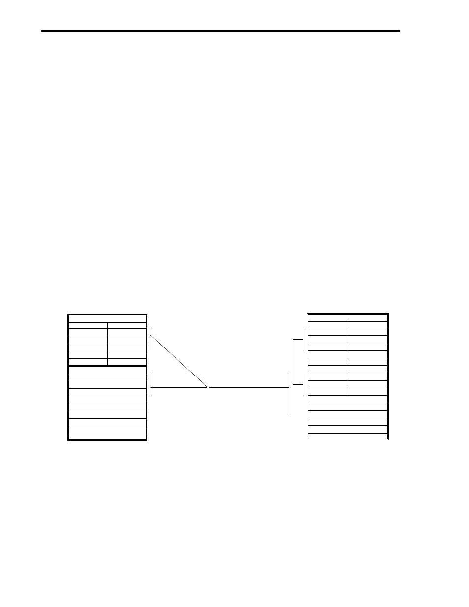
6.4.10 READING L- AND C-VALUES TOGETHER
Read Function Code 3 - Read Holding Registers, or Read Function Code 4 - Read Input Registers.
Because these commands are word oriented, only an even number of L-bytes can be transferred to
the PCS. If an attempt is made to transfer an odd number of L-bytes, the next lower even number
will be used. To facilitate transferring L- and C-values together, the requested L-bytes must first
be moved by the user from the PLC L-value memory segment to the top of the C-value memory
segment before all of data is sent to the PCS (see Figure 6-5). At the PCS the L-bytes are sepa-
rated from the C-words before each data stream is stored into its respective memory area. The L-
values are stored in the L-memory area on byte boundaries and the C-values are stored in the
C-memory area on word boundaries.
1. AN EVEN NUMBER OF L-VALUES ARE MOVED BY THE USER
TO THE TOP OF THE PLC C-VALUE MEMORY SEGMENT.
(NEXT LOWEST EVEN NUMBER IS USED AT THE PCS IF AN
ODD NUMBER OF L-VALUES ARE SPECIFIED.)
2 REQUESTED L-VALUES, FOLLOWED BY C-VALUES, ARE SENT
TO THE PCS.
3. AT THE PCS, THE L-VALUES ARE STORED IN THE L-MEMORY AREA.
4. AT THE PCS, THE C-VALUES ARE STORED IN THE C-MEMORY AREA.
Figure 6-5. Reading L- and C-Values
1
2
3
4
FUNCTION CODE 3 - READ HOLDING REGISTERS OR FUNCTION CODE 4 - READ INPUT REGISTERS
EVEN NUMBER OF L-BYTES
PCS DDI-A L-VALUES
LSB MSB
LSB MSB
L1536
L1536+n
L2047
PCS DDI-A C-VALUES
C704
C704+n
C767
LSB MSB
PLC L-VALUES
LSB MSB
LSB MSB
L0
Ln
NOT USED
NOT USED
NOT USED
NOT USED
PLC C-VALUES
L0
Ln
C0
Cn
NOT USED
NOT USED
LSB MSB
53MC9015 53MC5000 PLC and Printer Interfaces
6-4
MODBUS2