5 koyo header block command byte, 6 control bytes for koyo, Table 8-1. apb setup bytes for koyo – Micromod Micro-DCI: 53MC5000 PLC AND PRINTER INTERFACES User Manual
Page 95: Table 8-2. plc control and status bytes for koyo
8.5 KOYO HEADER BLOCK COMMAND BYTE
The two command codes that are used in the read/write byte of the Koyo DirectNET header block
are 30 for read and 38 for write.
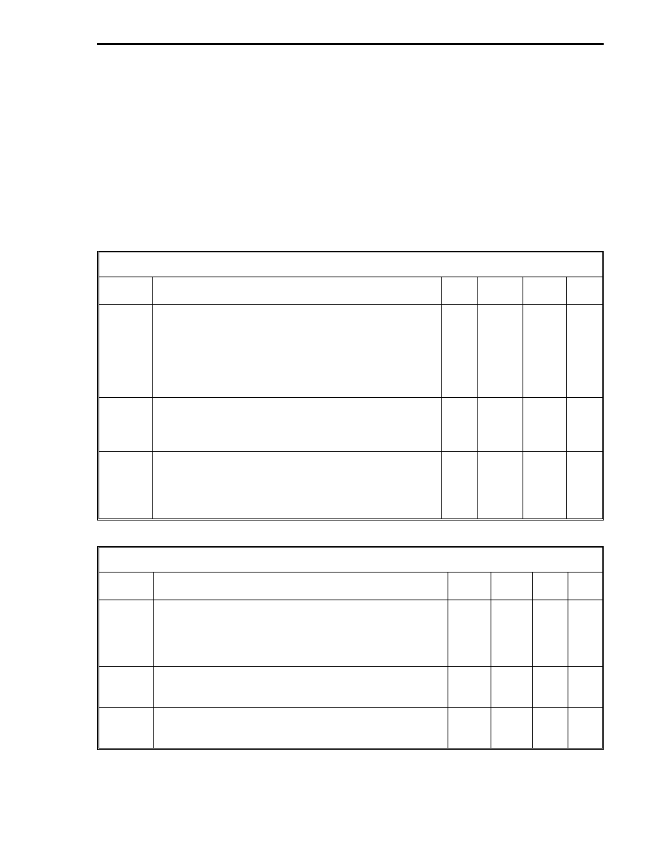
8.6 CONTROL BYTES FOR KOYO
The APB Setup Bytes, PLC Control and Status Bytes, PLC Read Control Bytes, and PLC Write
Control Bytes are presented in Tables 8-1 through 8-4. If any Control Byte is changed during
operation, it takes up to 10 seconds to become effective. (There is a 10 second interval be-
tween PCS checks for setup changes.)
Table 8-1. APB Setup Bytes for Koyo
Title
Definition
Set
By
DDI-A
DDI-B
De-
fault
Mode
It indicates the APB communications functionality as
follows:
0 = Off, 5 = Koyo
This datapoint should be left at 0 and configured to
a 5 after all of the other control bytes are
configured because setting this datapoint causes
the Koyo PLC Interface functionality to start.
User
B290
B456
0
Baud
Rate
It designates the data transfer rate as follows:
10 = 38400, 9 = 28800, 8 = 14400, 7 = 19200,
6 = 9600, 5 = 4800, 4 = 2400, 3 = 1200, 2 = 600,
1 = 300, 0 = 110
User
B292
B458
0
Set-Up
It designates the data format transfer protocol as
follows:
0 = 8 bits, 1 stop bit, no parity
1 = 8 bits, 1 stop bit, even parity
2 = 8 bits, 1 stop bit, odd parity
User
B293
B459
0
Table 8-2. PLC Control and Status Bytes for Koyo
Title
Definition
DDI-A DDI-B
Set
By
De-
fault
Setup
Error
It indicates the following: 0 = No Error, 1 = L-words to
read > 32, 2 = C-words to read > 64, 3 = L-words to
write > 32, 4 = C-words to write > 64, 5 = Memory type
not 31, 10 = Scan Time at 0. These error codes cause
DDI channel operation to halt.
B684
B660
Soft-
ware
0
Scan
Time
It is the PCS time period for the read and write phases
of a PCS-PLC transaction. It is entered as a number
from 1 to 255 which represents 100 to 25,500 ms.
B685
B661
User
0
Scan
Overruns
Counter*
This counter is incremented each time the read-write
phases exceed the specified Scan Time. It indicates the
Scan Time should be increased
B686
B662
Soft-
ware
0
*User can reset by writing zeros into the datapoints.
Section 8. Koyo Mode
KOYO
8-3