Micromod Micro-DCI: 53MC5000 PLC AND PRINTER INTERFACES User Manual
Page 52
5.2.2 PCS DATABASE MAP ANALOG LOCATIONS
As shown in Figures 5-1 and 5-2, the PCS can accomodate 64 C-values on eight contiguous ana-
log boards (32 through 39) maximum. Any combination of contiguous boards and modules can be
used, providing boards x modules does not exceed 64. It should be noted that even though
there may be unused modules on an analog board, there are no unused corresponding C-locations
in the PCS database. The PCS database expands to the module configuration as required. In ad-
dition to the rules given in Section 5.2, the user must specify the same number of PLC modules for
every board for analog board addresses 32-39. Control bytes are dedicated to this function as
shown in Figure 5-4.
In Figure 5-4, the PCS memory map C-datapoints are listed vertically in each module, e.g., C704
(DDI-A) and C640 (DDI-B) appear side-by-side in module 0 of board 32. Figure 5-4 therefore
shows how either DDI option can be mapped into the physical OPTO 22 board modules. Figure 5-
4 also illustrates the values that would be entered into the Analog I/O Control Bytes for the in-
stalled OPTO 22 configuration shown. The DDI-A datapoints are shown first, followed by the
DDI-B datapoints which are in brackets, e.g., DDI-A B677 [DDI-B B653].
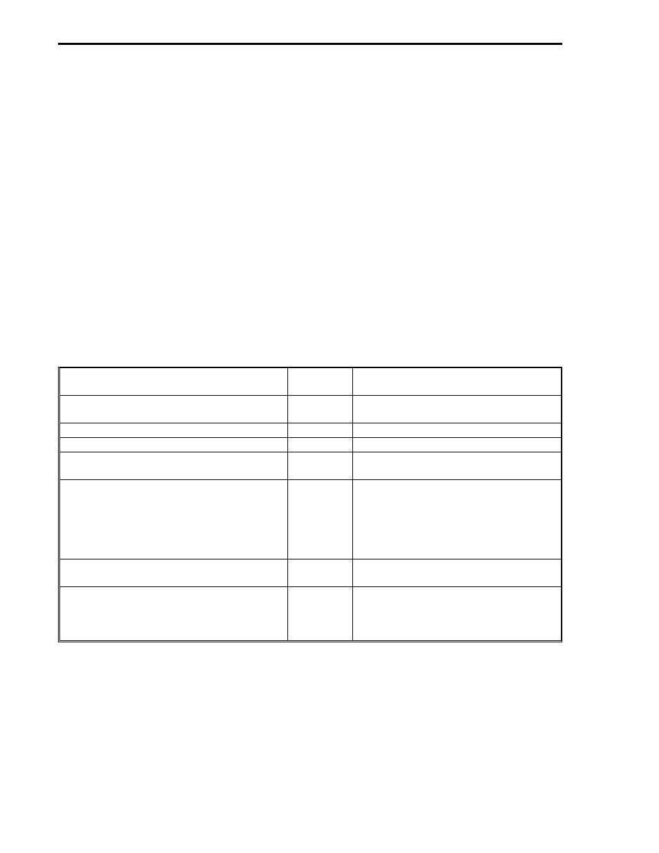
If it is assumed that board addresses 32 and 33 are installed with the module complements shown,
and a Read Input Average Data command is selected, then the DDI-A Digital I/O Control Bytes
listed in Table 5-4 would have the following values:
Title
DDI-A
Datapoint
Value Entered and Comments
Output Watchdog Delay Boards 32-39
B673
1, if a 10 second Watchdog delay time
is desired for Boards 32 and 33.
Number of Active Boards 32-39
B675
2, Boards 32 and 33.
Number of Analog Modules on Boards
B676
12, Boards 32 and 33.
Number of Analog Outputs
B677
8, for Boards 32 and 33, Modules 0
through 7.
Analog Input Type for Board Addresses 33
and 37, 32 and 36
B679
132, for Type 8 probe on Board 33 and
Type 4 probe on Board 32. 84
16
=
132
10
. As shown in Figure 5-4, Type 8
Probe is a Type T Thermocouple and
Type 4 Probe is a Type J
Thermocouple.
Analog Input Type for Board Addresses 35
and 39, 34 and 38
B680
0, for No Temperature Probe
Samples to Average
B681
3, for Read Input Average Data
command if selected, to indicate three
100 ms samples should be taken for
the average figure.
53MC9015 53MC5000 PLC and Printer Interfaces
5-6
OPTO