Table 10-1. parts replacement, 2 technical assistance, 3 parts list – Micromod Micro-DCI: 53MC5000 PLC AND PRINTER INTERFACES User Manual
Page 116: Table 10-2. parts list, 2 of 2
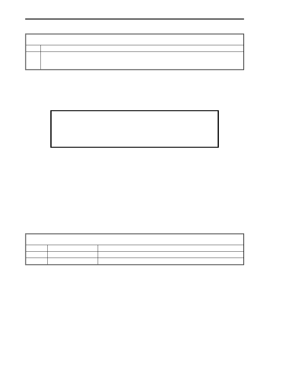
Table 10-1. Parts Replacement
Step
Procedure
13
To install the front display panel: Reconnect the ribbon cable to the display J5 socket.
Insert the display bottom tabs into the cabinet notches and push the front of the display to
latch it in place.
10.2 TECHNICAL ASSISTANCE
When replacing parts, should technical assistance be required, contact a MicroMod Automation Inc.
office.
NECESSARY ORDERING INFORMATION
When communicating with MMA for replacement of the main PCB,
reference the unit’s serial number to ensure the correct replacement
assembly is supplied. The necessary ordering information is provided
on the instrument data tag and on the manufacturing specification sheet
supplied with that particular controller.
In the event of a hardware malfunction, a replacement PCB can be quickly substituted for the defec-
tive assembly to minimize downtime. Contact MicroMod Automation Inc. for instructions before returning
equipment. The defective PCB should be carefully packaged and returned, shipping charges prepaid, to
the Repair Dept. Do not wrap PCBs in plastic, as it can cause static damage. It is suggested
that the defective PCB be returned in the special bag in which the replacement module was
supplied.
10.3 PARTS LIST
The parts list is provided in Table 10-2; see Figure 10-1.
Table 10-2. Parts List
Item
Part Number
Description
11 & 12 686B700U01
Auxiliary Processor Board (APB)
686B720U01
RS-232/485 ITB
2 of 2
53MC9015 53MC5000 PLC and Printer Interfaces
10-2
PARTS