Table 4-4. allen-bradley plc read control bytes – Micromod Micro-DCI: 53MC5000 PLC AND PRINTER INTERFACES User Manual
Page 39
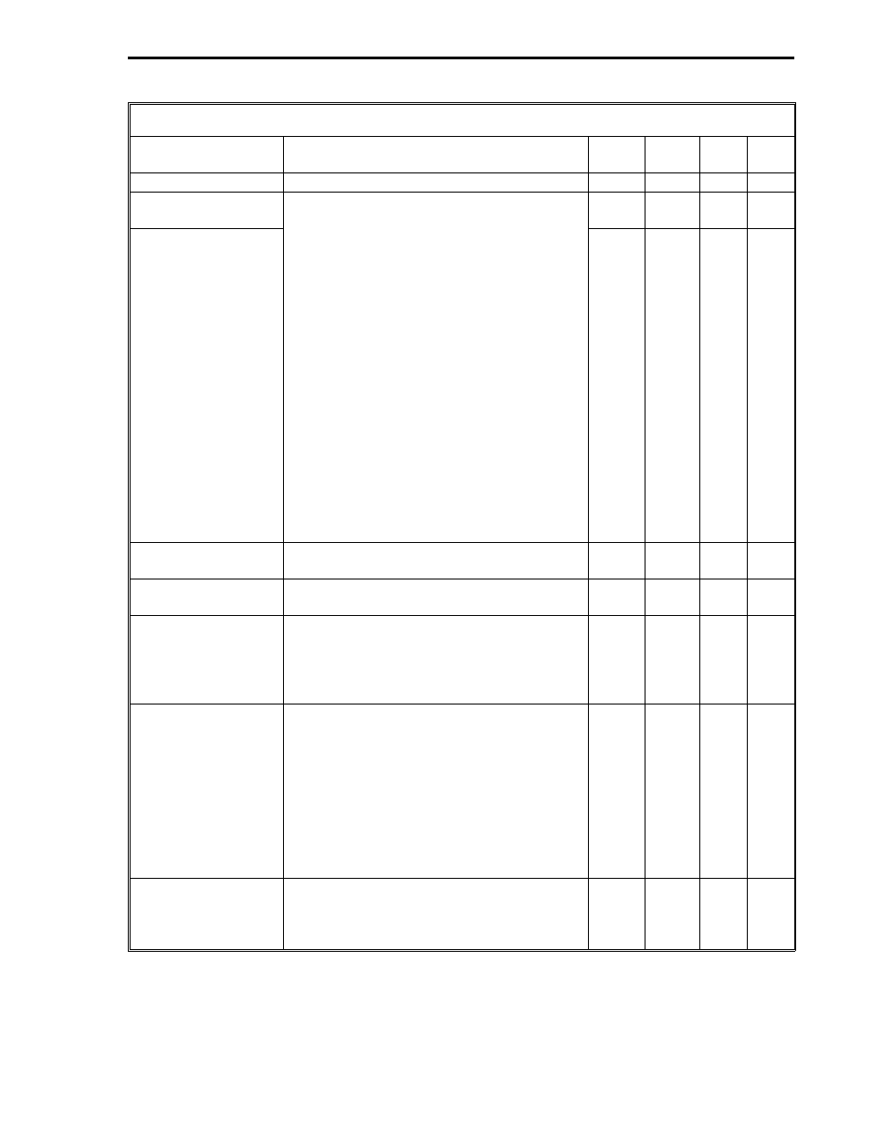
Table 4-4. Allen-Bradley PLC Read Control Bytes
Title
Definition
DDI-A DDI-B
Set
By
De-
fault
PLC Address
It is the address of the PLC to be accessed. B664
B640
User
0
Starting PLC Memory
Address (Low)
The two byte PLC memory starting address.
Each byte is a decimal number; however,
both bytes together function as a 16 bit
unsigned binary integer, e.g., the PLC octal
address 2764
8
= 00000101 11110100
2
=
05F4
16
(0000 0101 1111 0100). 5
16
= 5
10
,
therefore 5 is entered as the high byte B666
[or B642]. F4
16
= 244
10
therefore 244 is
entered as the low byte B665 [or B641]. If
the PLC address is a hexadecimal 4180
16
,
41
16
= 65
10
and 80
16
= 128
10
; therefore,
65
10
would be entered as the high byte
B666 [or B642] and 128
10
would be entered
as the low byte B665 [or B641]. (See
Appendix A for decimal conversions.) This
value may have to be doubled and must
be an even number for some byte
address oriented Allen-Bradley PLC’s.
Reference the appropriate Allen-Bradley
documentation.)
B665
B641
User
0
Starting PLC Memory
Address (High)
B666
B642
User
0
Number of L-Words
to Read
The number of L-words that are to be
accessed from the PLC.
B667
B643
User
0
Number of C-Words
to Read
The number of C-words that are to be
accessed from the PLC.
B668
B644
User
0
PLC Error Code*
(Reply Status)
The status codes are reported in decimal;
however, they are listed in hexadecimal in
the PLC manual. 255 = no reply; 00 =
Success - No Error. See the PLC book for
the Remote STS (Status) Error Codes.
B671
B647
Soft-
ware
0
Communications
Error Code*
0 = no errors. 255 = timeout error - a
timeout error indicates no response came
back from the PLC. 254 = bad checksum
(CRC) - a bad checksum indicates even
though the frame was formatted properly,
the data can not be used. 253 = bad
message - bad message indicates that
errors were found in the predictable portion
of the message from the PLC. 252 and 251
= PCS hardware malfunction.
B672
B648
Soft-
ware
0
Error Count*
This byte is a running total of PLC Error
Code responses that are not 00 (Success -
No Error) and non-zero Communications
Error Codes.
B673
B649
Soft-
ware
0
*User can reset by writing zeros into the datapoints.
Section 4. Allen-Bradley Mode
ALLEN
4-5