Table 6-1. pcs modbus master commands, 1 of 2 – Micromod Micro-DCI: 53MC5000 PLC AND PRINTER INTERFACES User Manual
Page 70
6.4.12 PCS MODBUS MASTER COMMANDS
The PCS Modbus RTU interface application uses Initialization, Read, and Write Modbus messages
to communicate with the PLC. During InItialization, the PCS sends a Restart Communications Op-
tion function to the PLC. The Read Modbus message causes data (L-values, C-values, or L- and
C-values) to be sent from the Modbus PLC to the PCS master, and the Write Modbus message
causes data (L-values, C-values, or L- and C-values) to be sent from the PCS master to the Mod-
bus PLC. The Modbus command set that is used for the Modbus messages is listed in Table 6-1
as follows:
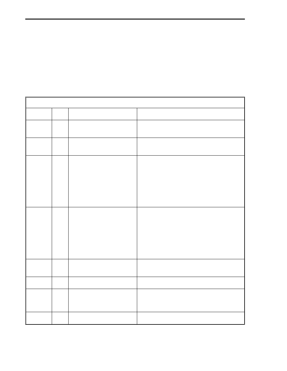
Table 6-1. PCS Modbus Master Commands
Function
Code
Data
Type
Title
Description
1
L
Read Coil [Output] Status
This command obtains the current status
(ON/OFF states) of a group of logic coils (L-
values).
2
L
Read Input Status
This command obtains the current status
(ON/OFF states) of a group of discrete inputs
(L-values).
3
L and
C
Read Holding Registers
This command obtains the current binary value
contained in one or more holding registers (C-
values). It can also be used to obtain L-values
stored in other PLC memory segments;
however, those L-values must first be moved
by the user into the lower memory addresses
(top) of the holding register memory segment
before the L- and C-values are read from the
memory.
4
L and
C
Read Input Registers
This command obtains the current binary value
contained in one or more input registers (C-
values). It can also be used to obtain L-values
stored in other PLC memory segments;
however, those L-values must first be moved
by the user into the lower memory addresses
(top) of the input register memory segment
before the L- and C-values are read from the
memory.
5
L
Preset [Write] a Single Coil
This command causes the last bit of the L-
memory area (DDI-A - L2047, DDI-B - L1535)
to be written to a single coil in the PLC.
6
C
Preset [Write] Single Holding
Register
This command places a binary value into a
holding register.
8
N/A Loopback Diagnostic Test
This command provides an assortment of
Diagnostic Code functions to help evaluate
Modbus communications processing. It is
described in greater detail in Section 6.4.12.
15
L
Force [Write] Multiple Coils
This command forces a series of consecutive
logic coils to specified ON or OFF states.
1 of 2
53MC9015 53MC5000 PLC and Printer Interfaces
6-6
MODBUS2