2 of 2 – Micromod Micro-DCI: 53MC5000 PLC AND PRINTER INTERFACES User Manual
Page 74
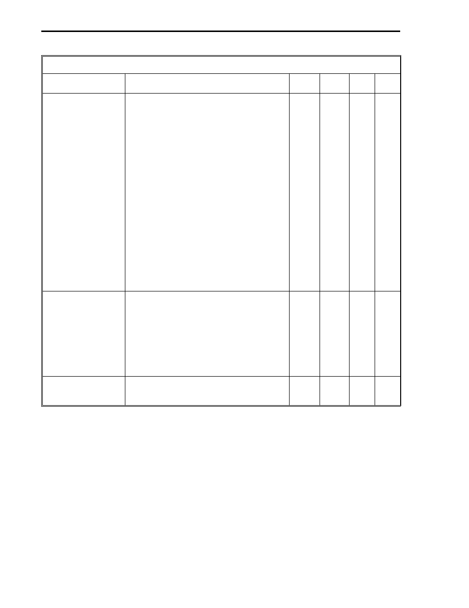
Table 6-4. Read Control Bytes for PCS Modbus Master
Title
Definition
DDI-A DDI-B
Set
By
De-
fault
PLC Error Code*
(Exception Response
Code)
Exception Response Codes 1-7 can be sent
from the PLC to the PCS master (see the
Modbus documentation for complete
definitions.)
01 - Illegal Function: Does not exist as a
valid function code.
02 - Illegal Data Address: Not an allowable
address.
03 - Illegal Data Value: The fetch quantity
requested is not allowed.
04 - Failure In Associated Device: The
slave failed to respond to the message.
05 - Acknowledge: The slave has accepted
and is processing a long duration
command.
B671
B647
Soft-
ware
0
06 - Busy, Rejected Message: The slave is
busy processing a long duration com-
mand.
07 - NAK, Negative Acknowledgement: The
program function just requested can not
be performed.
Communications
Error*
0 = no errors. 255 = timeout error - a
timeout error indicates no response came
back from the PLC. 254 = bad checksum
(CRC) - a checksum indicates even though
the frame was formatted properly, the data
can not be used. 253 = bad message - bad
message indicates unexpected data was
found in the reply from the PLC. 252 and
251 = PCS hardware malfunction.
B672
B648
Soft-
ware
0
Error Count*
This byte is a running total of the Exception
Response Codes and the Communication
Errors listed above.
B673
B649
Soft-
ware
0
*User can reset by writing zeros into the datapoints.
2 of 2
53MC9015 53MC5000 PLC and Printer Interfaces
6-10
MODBUS2