Micromod Micro-DCI: 53MC5000 PLC AND PRINTER INTERFACES User Manual
Page 50
5.2.1 PCS DATABASE MAP DIGITAL LOCATIONS
In Figures 5-1 and 5-2, each of the board’s 16 digital modules map into 16 L-datapoints as shown.
In addition to the rules given in Section 5.2, the user must specify the same number of PLC mod-
ules for every even and odd board for digital board addresses 0-15 and 16-31. Control bytes are
dedicated to this function as shown in Figure 5-3.
In Figure 5-3, the PCS memory map L-datapoints are listed vertically in each module, e.g., L1536
(DDI-A) and L1024 (DDI-B) appear side-by-side in module 0 of board 0. Figure 5-3 therefore
shows how either DDI option can be mapped into the physical OPTO 22 board modules. Figure 5-
3 also illustrates the values that would be entered into the Digital I/O Control Bytes for the installed
OPTO 22 configuration shown. The DDI-A datapoints are shown first, followed by the DDI-B data-
points which are in brackets, e.g., DDI-A B667 [DDI-B B643].
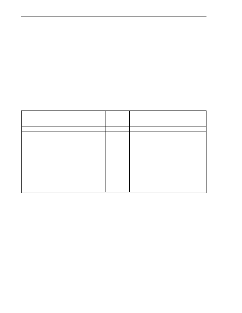
If it is assumed that board addresses 0, 1, 16, and 17 are installed with the module complements
shown, then the DDI-A Digital I/O Control Bytes listed in Table 5-3 would have the following values:
Title
DDI-A
Datapoint
Value Entered and Comments
Number of Active Boards 00-15
B665
2, Boards 0 and 1.
Number of Active Boards 16-31
B666
2, Boards 16 and 17.
Number of Output Modules for Even Board
Addresses 00-15
B667
10, for Board 0, Modules 0 through 9
(datapoints L1536 through L1545).
Number of Output Modules for Odd Board
Addresses 00-15
B668
12, for Board 1, Modules 0 through 11
(datapoints L1552 through L1563).
Number of Output Modules for Even Board
Addresses 16-31
B669
6, for Board 16, Modules 0 through 5
(datapoints L1792 through L1797).
Number of Output Modules for Odd Board
Addresses 16-31
B670
3, for Board 17, Modules 0 through 2
(datapoints L1808 through L1810).
Output Watchdog Delay Boards 00-15
B671
2, if a i minute Watchdog delay time is
desired for Boards 0 and 1.
Output Watchdog Delay Boards 16-31
B672
3, if a 10 minute Watchdog delay time
is desired for Boards 16 and 17.
It should be noted that whenever OPTOMUX PB4MD boards are used, then the last 12 of the 16 L-
values for each board must be skipped in the PCS memory map because these boards have only
four modules each.
53MC9015 53MC5000 PLC and Printer Interfaces
5-4
OPTO