Table 8-3. koyo plc read control bytes – Micromod Micro-DCI: 53MC5000 PLC AND PRINTER INTERFACES User Manual
Page 96
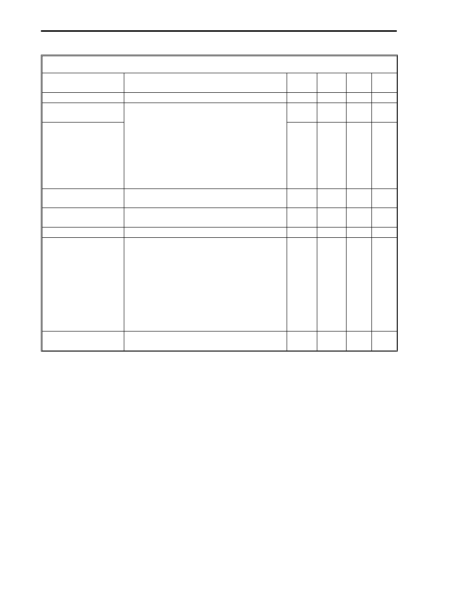
Table 8-3. Koyo PLC Read Control Bytes
Title
Definition
DDI-A DDI-B
Set
By
De-
fault
PLC Address
It is the address of the PLC to be accessed. B664
B640
User
0
Starting PLC Memory
Address (Low)
The two byte PLC memory starting address.
Each byte is a decimal number; however,
both bytes together function as a 16 bit
unsigned binary integer, e.g., the PLC
hexadecimal address 4180
16
would be
entered as 65
10
in the high byte B666 [or
B642] and 128
10
in the low byte B665 [or
B641]. (See Appendix A for decimal
conversions.)
B665
B641
User
0
Starting PLC Memory
Address (High)
B666
B642
User
0
Number of L-Words
to Read
The number of L-words that are to be
accessed from the PLC.
B667
B643
User
0
Number of C-Words
to Read
The number of C-words that are to be
accessed from the PLC.
B668
B644
User
0
Memory Type
This byte must be a 31.
B669
B645
User
0
Communications
Error Code*
0 = no errors. 255 = timeout error - a
timeout error indicates no response came
back from the PLC. 254 = bad checksum
(CRC) - a bad checksum indicates even
though the frame was formatted properly,
the data can not be used. 253 = bad
message - bad message indicates that
errors were found in the predictable portion
of the message from the PLC. 252 and 251
= PCS hardware malfunction.
B672
B648
Soft-
ware
0
Error Count*
This byte is a running total of the non-zero
Communications Error Codes
B673
B649
Soft-
ware
0
*User can reset by writing zeros into the datapoints.
53MC9015 53MC5000 PLC and Printer Interfaces
8-4
KOYO