Figure 6-6. writing l- and c-values, 11 writing l- and c-values together – Micromod Micro-DCI: 53MC5000 PLC AND PRINTER INTERFACES User Manual
Page 69
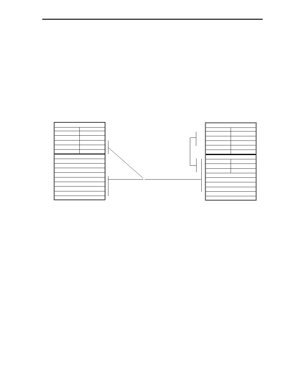
6.4.11 WRITING L- AND C-VALUES TOGETHER
Write Function Code 16 - Preset [Write] Multiple Holding Registers.
Because this command is word oriented, only an even number of L-bytes can be transferred to the
PLC. If an attempt is made to transfer an odd number of L-bytes, the next lower even number will
be used. To facilitate transferring L- and C-values together, the L-bytes and C-words are first
moved from the PCS to the PLC C-value memory segment. The L-values, which are at the top of
the PLC C-value memory segment, must then be moved by the user to the L-value memory seg-
ment (see Figure 6-6). The L-values are stored in the PLC L-value memory segment and the C-val-
ues are stored in the C-value memory segment.
1. AN EVEN NUMBER OF L-VALUES ARE FETCHED FROM
THE BOTTOM OF THE PCS L-MEMORY AREA. (NEXT LOWEST EVEN
NUMBER IS USED AT PCS IF AN ODD NUMBER OF L-VALUES
ARE SPECIFIED.)
2. C-VALUES ARE FETCHED FROM THE BOTTOM OF THE PCS
C-MEMORY AREA.
3. THE L- AND C-VALUES ARE TRANSFERRED TO THE PLC
C-VALUE MEMORY SEGMENT.
4. AT THE PLC, USER MOVES L-VALUES FROM THE TOP OF
THE C-VALUE MEMORY SEGMENT TO THE L-VALUE MEMORY
SEGMENT.
Figure 6-6. Writing L- and C-Values
4
3
1
2
FUNCTION CODE 16 - PRESET [WRITE] MULTIPLE HOLDING REGISTERS
EVEN NUMBER OF L-BYTES
PCS DDI-A L-VALUES
LSB MSB
LSB MSB
L1536
L2000
L2047
PCS DDI-A C-VALUES
C704
C764
C767
LSB MSB
PLC L-VALUES
LSB MSB
LSB MSB
L0
Ln
NOT USED
NOT USED
NOT USED
NOT USED
PLC C-VALUES
L0
Ln
C0
Cn
NOT USED
LSB MSB
Section 6. MODBUS RTU Mode
MODBUS2
6-5