Gf100 series – Brooks Instrument GF126 User Manual
Page 48
4-4
GF100 Series
Installation and Operation Manual
X-TMF-GF100-Series-MFC-eng
Part Number: 541B137AAG
March, 2013
Section 4 Maintenance & Troubleshooting
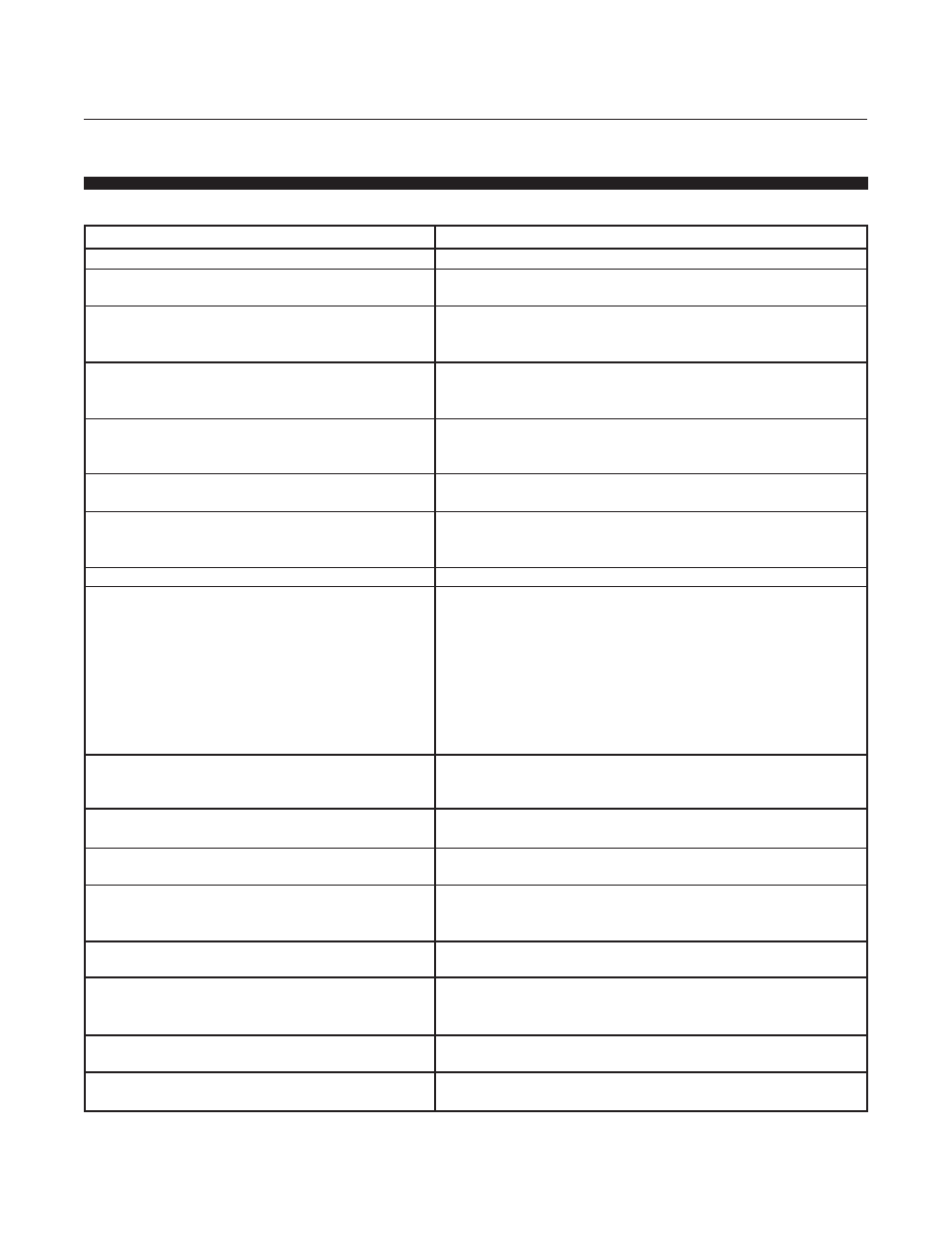
4-5 GF100 Series Troubleshooting Guide
Symptoms & Possible Causes
Corrective Action
1. No gas flow.
Is the gas supply turned on?
Check shut-off valve and pressure readout. Open
the gas supply.
Is the regulator turned on at the
Turn off the regulator and reset it to the
correct operating pressure?
recommended pressure as described in the
Data Sheet.
Are any upstream or downstream
Verify that the valves are open and operating
shut-off valves closed, either by
properly.
the system or because of failure?
Is the MOD LED light on the GF100 Series
Observe the LED display panel on top of to
lit solid green?
verify. If the LED light is not lit, cycle power the
to reboot.
Is the commanded setpoint from
Use the tool software to verify.
tool/system at 0.00 Vdc?
Has the been commanded
Use the tool software to verify.
off by an active “valve
closed” input?
2. Flow out of range.
Is the gas inlet/outlet pressure differential
Verify that the pressure is correct for the gas
either too high or too low?
and range. If required, adjust inlet/outlet pressure
to achieve proper pressure reading.
NOTE: If the differential pressure is too high,
voltage to the will be zero, which is
abnormally low for the setpoint. If the
differential is too low, voltage to will
be at its maximum value, which is abnormally
high for the set-point.
Is the MOD LED light on the GF100 Series
Observe the LED display panel at top of .
lit solid green?
If the LED light is not lit, cycle power the to
reboot.
Is the setpoint correct for the
Use the tool software to verify.
required gas flow?
Is the calibrated for the
Check the side label. Run a
particular gas?
flow check to verify.
Is the zero correct?
Zero the according to zeroing
procedure in Section 2-14. Verify leak check rates
are OK.
3. No gas control; flow is at or
above maximum.
Is the gas pressure across the
Verify that the pressure is correct for the gas and
too high?
range. If required, adjust inlet/outlet pressure to
achieve proper pressure reading.
Are system valves open, or is the
Use tool software to verify.
purge input activated?
Is the setpoint correct for the
Use tool software to verify.
required flow?
Table 4-2 GF100 Series Troubleshooting Guide