Gf100 series, Warning – Brooks Instrument GF126 User Manual
Page 28
2-8
GF100 Series
Installation and Operation Manual
X-TMF-GF100-Series-MFC-eng
Part Number: 541B137AAG
March, 2013
Section 2 Installation
2-13 Perform a Leak Test
WARNING
!
It is critical to leak test the gas supply lines and GF100 Series connections
before turning on the process gas supply after any new installation. Check
for leaks using a helium leak detector or any other appropriate leak test
method. Follow leak test specifications as defined by integrator.
2-14 Zeroing Setup Process
The following steps are required before the GF100 Series is zeroed.
1. Make sure that the GF100 Series has been installed inside the
equipment (panel) for at least four hours and powered up at least one
hour prior to zeroing. This insures that the GF100 Series is in its "use
attitude" and is operating at normal temperature. If the GF100 Series is
subjected to a vacuum purge for more than one minute, turn off the
GF100 Series (ie., provide a zero setpoint) for a time period of twice the
vacuum purge time.
2. Refer to Figure 2-1. Open the upstream shut-off valve (5) and close the
downstream shut-off valve (7). This eliminates a pressure drop across
the GF100 Series and subsequent leakage from the PID control valve
inside the GF100 Series.
3. Provide a 100% setpoint to the GF100 Series for no longer than 60
seconds. This equalizes the pressure across the PID control valve.
4. Refer to Figure 2-1. Close the upstream shut-off valve (5) to prevent any
pressure effects from the regulator (3).
5. Close the GF100 Series and wait two minutes.
6. Read the output signal of the GF100 Series. This output signal is the
initial flow in percent of full scale. The output signal should be 0.0 (±
0.1%). If the output signal is too high, re-zero the GF100 Series as
described in Section 2-15.
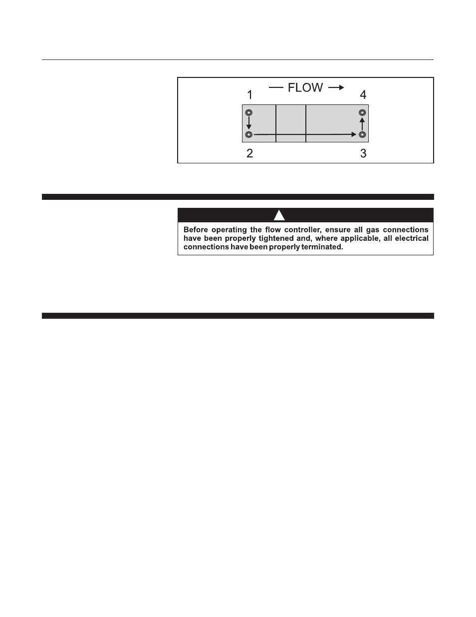
Figure 2-5 Mounting Screws Torque Pattern