Gf100 series – Brooks Instrument GF126 User Manual
Page 37
2-17
GF100 Series
Installation and Operation Manual
X-TMF-GF100-Series-MFC-eng
Part Number: 541B137AAG
March, 2013
Section 2 Installation
2-20 GF135 Inlet Valve Installation
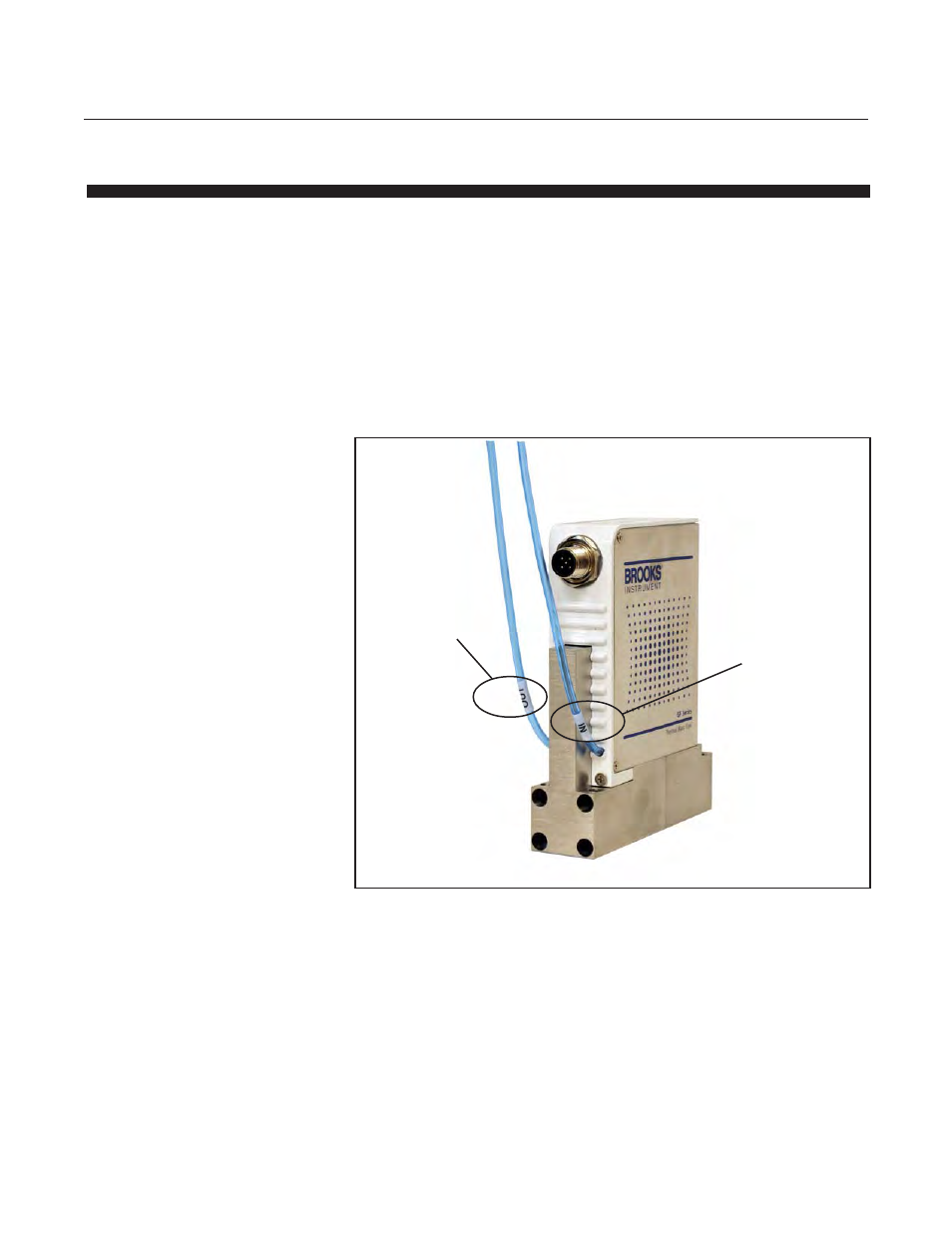
When installing the GF135 –
1. The inlet pneumatic isolation valve supply line needs to be disconnected
from the inlet pneumatic isolation valve.
2. Next the inlet valve supply line needs to be connected to the inlet tube on
the MFC. The tube is labeled ‘IN’ and a connector is provided with the
GF135 to connect the customer inlet valve supply tube to the MFC ‘IN’ tube.
3. Next the MFC tube labeled ‘OUT’ should be connected to the customer
inlet pneumatic isolation valve.
Note – The air passes through a failsafe normally open valve inside the
GF135 and is connected back to the inlet isolation valve. For safe operation
and in line with S2 compliance, the GF135 cannot override and open the
inlet isolation valve.
Figure 2-17 GF135 Series Showing Inlet/Outlet Pneumatic Isolation Valve Lines
Outlet - Pneumatic
Isolation Valve Line
Inlet - Pneumatic
Isolation Valve Line