Gf100 series – Brooks Instrument GF126 User Manual
Page 35
2-15
GF100 Series
Installation and Operation Manual
X-TMF-GF100-Series-MFC-eng
Part Number: 541B137AAG
March, 2013
Section 2 Installation
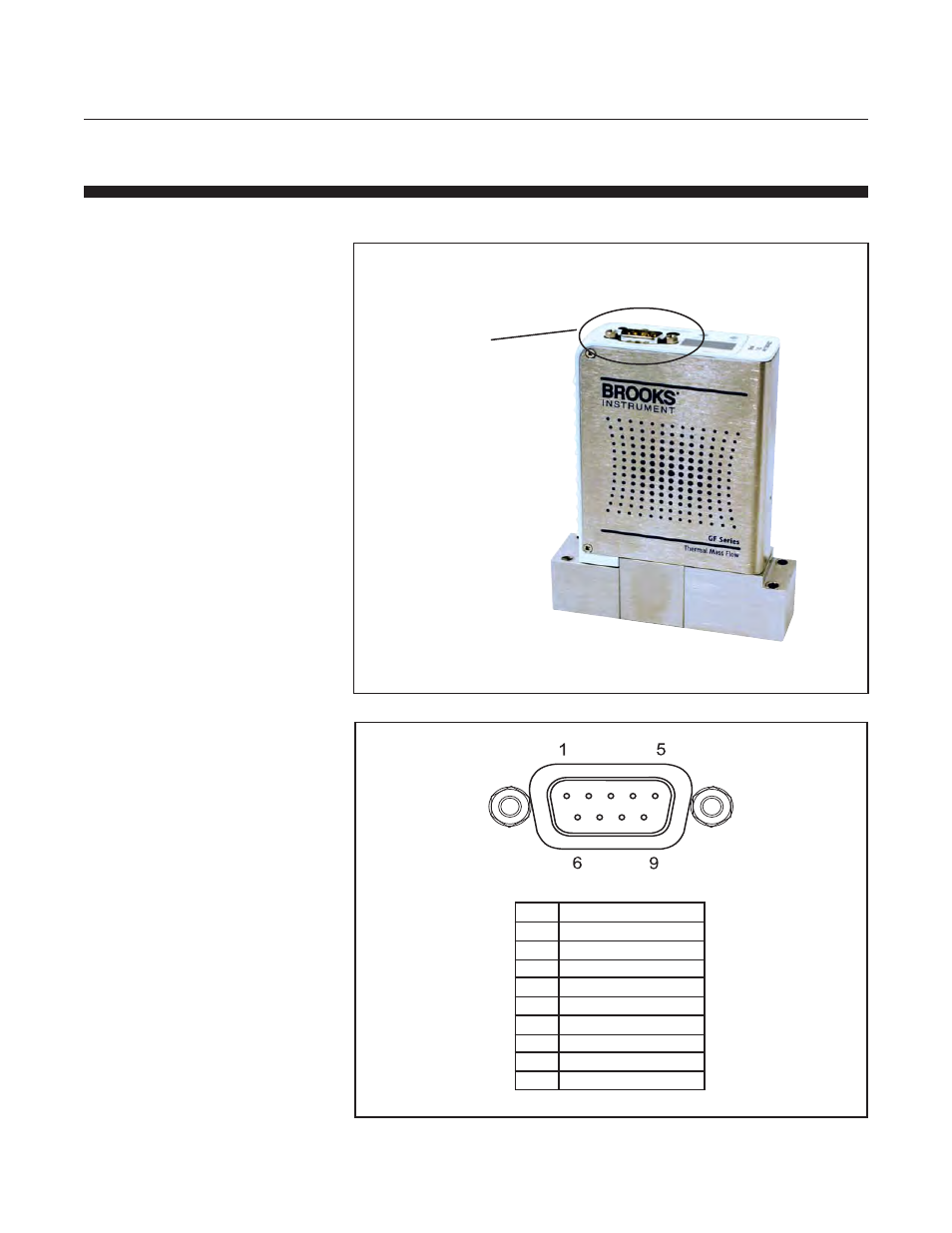
Figure 2-15 Analog 9-Pin Connector (M)
PIN
Connection
1
Valve Control
2
Output (0-5 Vdc)
3
+15 Vdc
4
Power Common
5
-15 Vdc
6
Setpoint (0-5 Vdc)
7
Signal Common
8
RS485 DX+
9
RS485 DX-
Figure 2-14 GF100 Series with 9-Pin Analog Connector
Analog 9-Pin
Connector
(Refer to Figure 2-15
for Pin-Out Details)
2-19-2 Analog/RS485 Connections
The GF100 Series devices are available with Analog 9-Pin D-Connectors
shown in Figure 2-14.
This manual is related to the following products: