Gf100 series – Brooks Instrument GF126 User Manual
Page 26
2-6
GF100 Series
Installation and Operation Manual
X-TMF-GF100-Series-MFC-eng
Part Number: 541B137AAG
March, 2013
Section 2 Installation
2-12 Position and Mount the GF100 Series
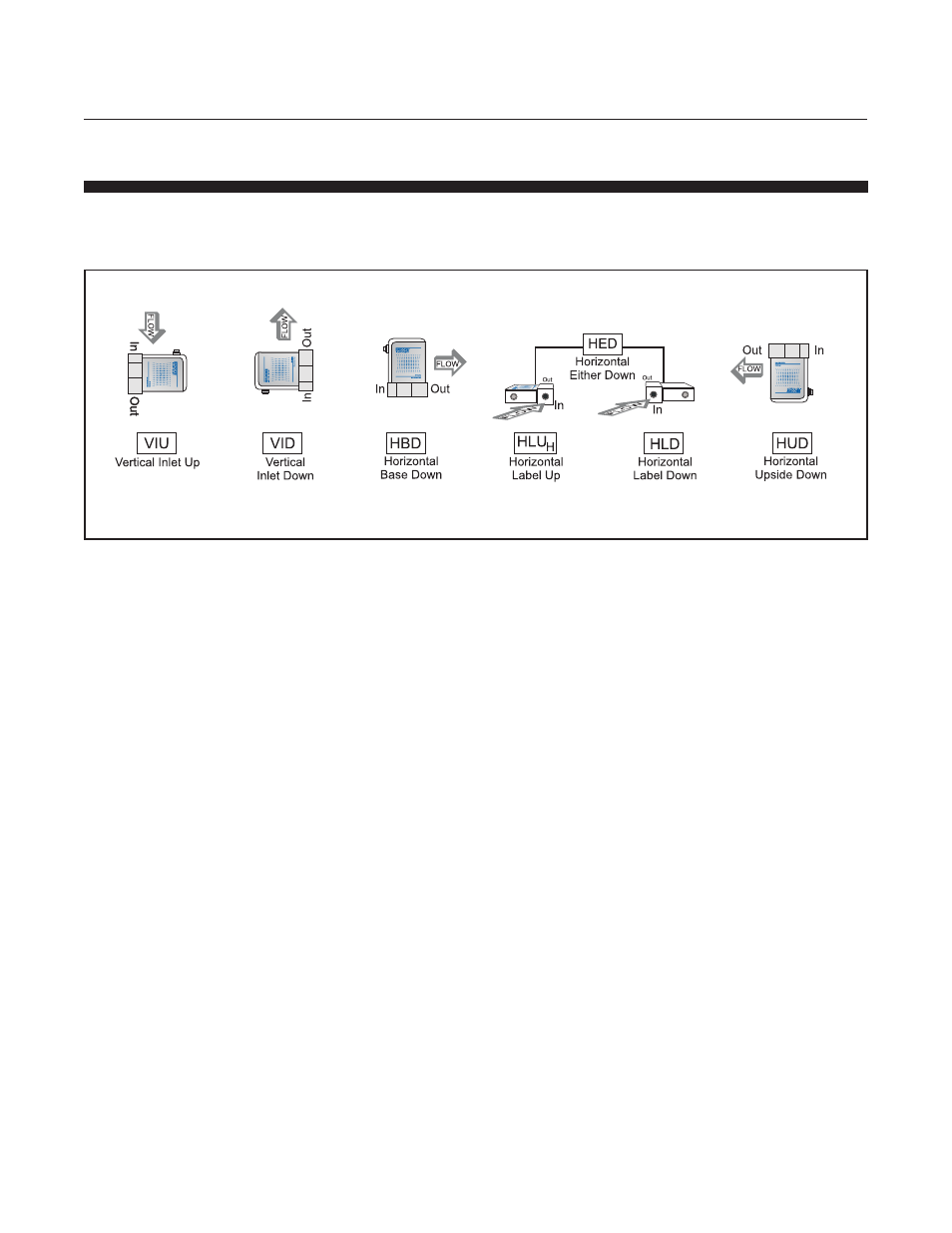
Position the GF100 Series so that the gas flow is pointed in the direction of
the grey arrow on the GF100 Series label. The various mounting positions
are described in Figure 2-3
The standard orientation for the GF100 Series is Horizontal Base Down (HBD).
The GF125 & GF135 employ a proprietary algorithm that utilizes the internal
pressure sensor to compensate for potential orientation effects when the
MFC is used with certain higher density gases. Non HBD mounting
orientations can be selected by using the MultiFlo software.
In the case of the GF100/120 Series, which does not have an internal
pressure sensor, it is recommended that the MFC is re-zeroed with process
gas following the recommended Brooks procedure (see zeroing bulletin
FSB-001-0015 for futher information).
If your GF100 Series is configured with downported fittings, follow Steps 1
though 4 below. If your GF100 Series has VCR fittings, proceed to Step 5.
1. Refer to Figure 2-4. If downported fittings (1) are used, the GF100
Series is mounted to K1 Series substrate blocks (2) with four screws
(3). Metal C-seals or W-seals (4) (as provided by integrator) are
inserted between the GF100 Series and substrate blocks before the
screws are installed. These metal seals must be replaced after each
installation.
2. Select the mounting screws noted in Table 2-1 below for downported
devices. M4 screws are used on 1.125" devices, K1S. M5 screws are
used on 1.5" devices, K1R2 and K1H.
3. Refer to Figure 2-4. Insert the two mounting seals (4) over the gas flow
path of the K1 block. Carefully align the GF100 Series mounting holes
onto the K1 substrate blocks. Using your fingers, install the screws
through the GF100 Series fitting and hand tighten.
Figure 2-3 GF100 Series Mounting Attitude Positions