Gf100 series – Brooks Instrument GF126 User Manual
Page 32
2-12
GF100 Series
Installation and Operation Manual
X-TMF-GF100-Series-MFC-eng
Part Number: 541B137AAG
March, 2013
Section 2 Installation
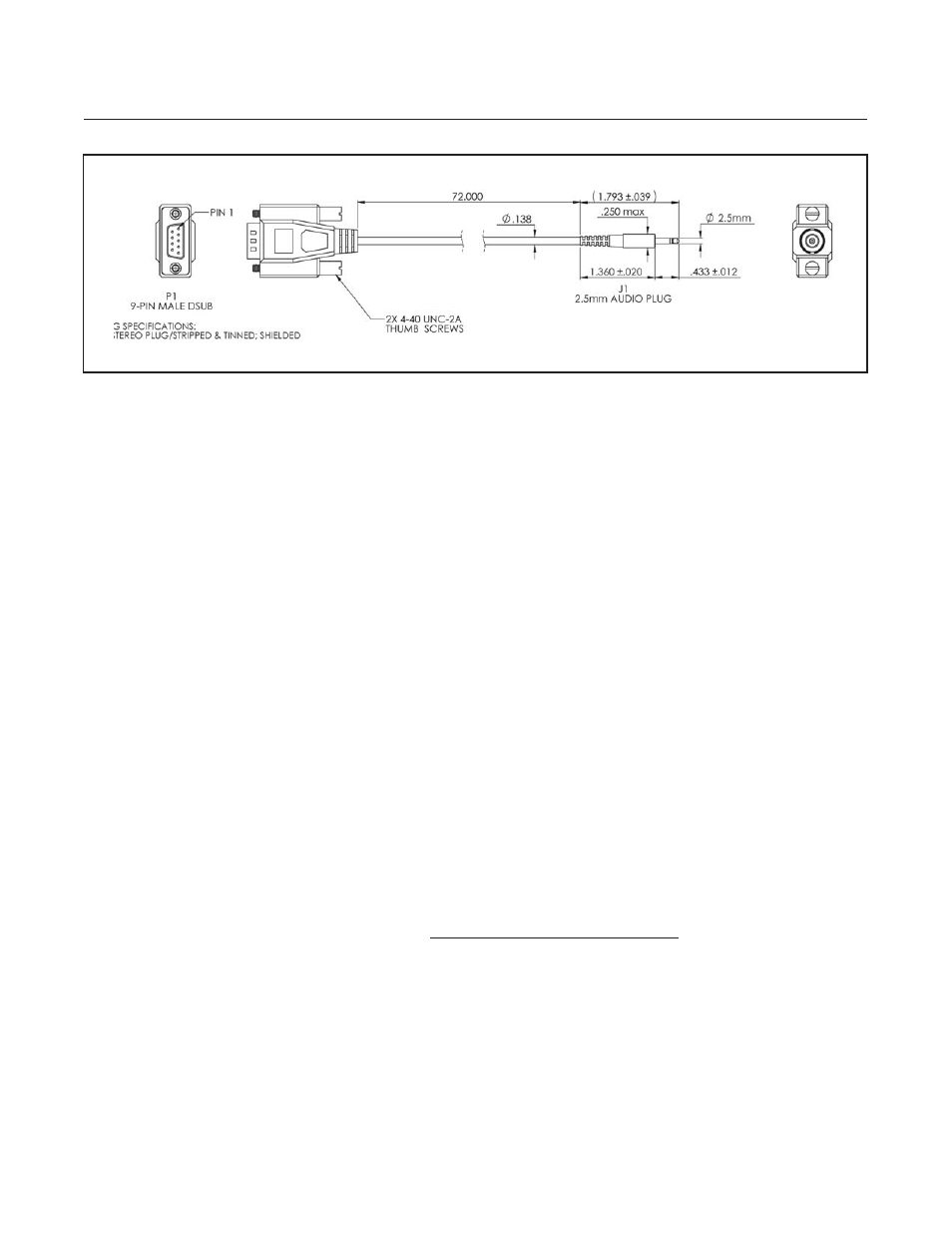
Figure 2-10 MultiFlo Cable Adaptor
The MultiFlo Configurator interfaces to the GF Series device through RS485
or DeviceNet communications. There are various ways to connect the
device regardless of device configuration. Devices may be connected
through the diagnostic port using cables in one of the two Basic MultiFlo
Configurator Kits or DeviceNet devices can alternatively be connected
using a National Instruments or SST DeviceNet scanner card.
778Z010ZZZ Basic MultiFlo Configurator Kit
A331710003 Cable Assembly 2.5mm
A332300001 Converter 232/485
778Z011ZZZ Basic MultiFlo Configurator Kit
w/Power Supply and Adapter Cables
A331710003 Cable Assembly 2.5mm
A332300001 Converter 232/485
A332295001 Power Supply MFC
A332297002 Cable, Power, 9-Pin
A332297001 Cable, Power, DeviceNet
Connect the MultiFlo Cable Adapter 2.5mm jack to the Diagnostic Port on
the top of the device. See Figure 2-12.
Connect the RS-485 end of the converter to the 9-Pin RS-485 end of the
MultiFlo Cable Adapter.
Connect the RS-232 end of the converter to the Serial Port of a laptop or PC.
The latest MutliFlo Configurator Software and Databases and MultiFlo
Configurator Quick Start Guide are available on the Brooks Instrument
website at: www.BrooksInstrument.com/MultiFlo. Please reference the