Gf100 series – Brooks Instrument GF126 User Manual
Page 27
2-7
GF100 Series
Installation and Operation Manual
X-TMF-GF100-Series-MFC-eng
Part Number: 541B137AAG
March, 2013
Section 2 Installation
4. Using a torque wrench and a metric hex key, tighten the screws to the
torque value as described in Table 2-2 and Torque Pattern Figure 2-5.
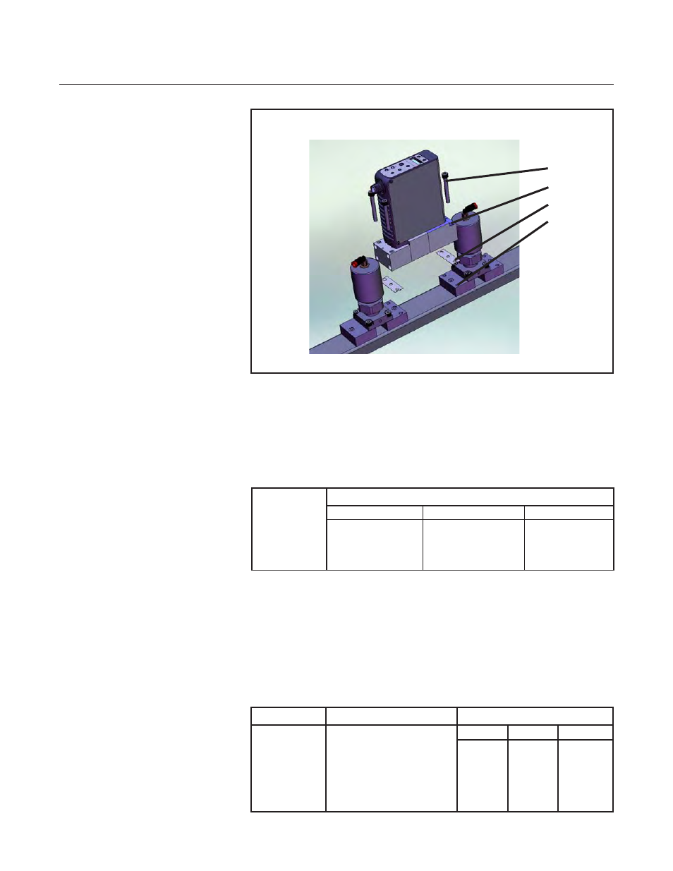
Figure 2-4 GF 100 Series Mounted to K1 Series Substrate Blocks
1
3
4
2
Table 2-1 K1 Series Fasteners
Connection
GF 100 Series
to
Subtstrate
Fastener Size
K1S
K1R2
K1H
M4 x 34mm
M5 x 30mm
M5 x 37mm
or
M4 x 35mm
5. If your GF100 Series is configured with ¼" VCR fittings, secure the
GF100 Series block to the gas panel with two, 8-32-UNC-2B" screws.
Then connect the inlet/ outlet fittings to the gas supply line using two
wrenches. Tighten the fittings to manufacturer recommendations.
Table 2-2 K1 Substrate Torque Data
Connection
GF125 to
Subtstrate
Torque Pattern
Use a square pattern as
shown in Figure 2-5.
Start at 25 inch-pounds and
increase in increments of
10 inch-pounds until proper
value is obtained.
Torque (Inch-Pounds)
K1S
K1R2
K1H
45
45
45