Gf100 series, Base i/o options, Pdc ordering code g1 – Brooks Instrument GF126 User Manual
Page 36: Pdc ordering code dx, Pdc ordering code tx, Pdc ordering code bb
2-16
GF100 Series
Installation and Operation Manual
X-TMF-GF100-Series-MFC-eng
Part Number: 541B137AAG
March, 2013
Section 2 Installation
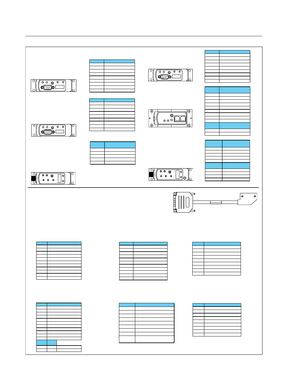
I/O Options Using Base Model and Adapter Cable
A range of low profile adapter cables have been deveoped to support replacing older
generation MFC's with different pinout configurations. The base MFC will be either a, G1,
TX or SX configuration, depending on the product being replaced.
PDC Ordering Code: EX
PDC Ordering Code: EX
PDC Ordering Code: EX
PDC Ordering Code: EX
PDC Ordering Code: EX
Description: GX base I/O with
7003083 adapter for compatability
with Unit “E”, IN “L”, “R”
PDC Ordering Code: KX
PDC Ordering Code: KX
PDC Ordering Code: KX
PDC Ordering Code: KX
PDC Ordering Code: KX
Description: G1 base I/O with
7003298 adapter for compatability
with Unit UDK15
PDC Ordering Code UX
PDC Ordering Code UX
PDC Ordering Code UX
PDC Ordering Code UX
PDC Ordering Code UX
Description: SX base I/O with 7003550
adapter for
compatability with
Unit UDU15
PDC Ordering Code: T1
PDC Ordering Code: T1
PDC Ordering Code: T1
PDC Ordering Code: T1
PDC Ordering Code: T1
Description: TX base I/O with 7003551
adapter for
compatability with
IFlow DB15 & TN 15 pin
PDC Ordering Code: FX / JX
PDC Ordering Code: FX / JX
PDC Ordering Code: FX / JX
PDC Ordering Code: FX / JX
PDC Ordering Code: FX / JX
Description: SX base I/O with 7003069
(FX)/7001814 (JX)
adapter for compatability with
Unit UDF9/UDJ9
D-Sub
Pin No.
Signals
1
Valve Control
2
Output (0-5 Vdc)
3
+15 Vdc
4
Power Common
5
-15 Vdc
6
Setpo int (0-5 Vdc)
7
Signal Commo n
8
Signal Commo n
9
Va lve Test Point
RJ11 J2
Pin No.
Si gnals
3
RS-485 (DX+)
2
RS-485 (DX-)
PDC Ordering Code G1
PDC Ordering Code G1
PDC Ordering Code G1
PDC Ordering Code G1
PDC Ordering Code G1
(GF135 use Code G2)
(GF135 use Code G2)
(GF135 use Code G2)
(GF135 use Code G2)
(GF135 use Code G2)
Description: Industry standard
Analog / RS485 interface
PDC Ordering Code GX
PDC Ordering Code GX
PDC Ordering Code GX
PDC Ordering Code GX
PDC Ordering Code GX
Description: OEM specific
Analog / RS485 interface.
Display and top plate
re-oriented 180
o
Base I/O Options
Pin No.
Signals
1
Valve Control
2
Output (0-5 Vdc)
3
+15 Vdc
4
Power Common
5
-15 Vdc
6
Setpo int (0-5 Vdc)
7
Signal Commo n
8
RS-485 (DX+)
9
RS-485 (DX-)
Pin No.
Signals
1
Valve Control
2
Output (0-5 Vdc)
3
+15 Vd c
4
Power Common
5
-15 Vdc
6
Setpo int (0-5 Vdc)
7
Signal Commo n
8
RS-485 (DX+)
9
RS-485 (DX-)
PDC Ordering Code DX
PDC Ordering Code DX
PDC Ordering Code DX
PDC Ordering Code DX
PDC Ordering Code DX
(GF135 use Codes D0-D9
(GF135 use Codes D0-D9
(GF135 use Codes D0-D9
(GF135 use Codes D0-D9
(GF135 use Codes D0-D9
and DA-DX)
and DA-DX)
and DA-DX)
and DA-DX)
and DA-DX)
Description: Industry standard
ODVA compliant DeviceNet
interface
M12
Pin No.
Signals
1
Drain
2
V+ (11-25 Vdc)
3
V-
4
CAN-H
5
CAN-L
PDC Ordering Code TX
PDC Ordering Code TX
PDC Ordering Code TX
PDC Ordering Code TX
PDC Ordering Code TX
Description: Industry standard
Analog only interface
Pin No.
Signals
1
Valve Control
2
Output (0-5 Vdc)
3
+15 Vd c
4
Power Common
5
-15 Vdc
6
Setpo int (0-5 Vdc)
7
Signal Commo n
8
No Connection
9
No Connection
PDC Ordering Code BB
PDC Ordering Code BB
PDC Ordering Code BB
PDC Ordering Code BB
PDC Ordering Code BB
Description: Industry standard
ODVA compliant DeviceNet
interface, Plus a separate
Analog 0-5 Vdc Connector
PDC Ordering Code SX
PDC Ordering Code SX
PDC Ordering Code SX
PDC Ordering Code SX
PDC Ordering Code SX
Description: Industry standard
Analog 9-Pin Sub D connector
and dual RJ11 RS485 ports
Pin No
9
6
4
7
11
15
1,13,14
2
12
8
3,5,10
Signals
VALVE OFF
OUTPUT ( 0-5 VDC)
CASE GROUND
NO CONNECTION
+ 15 VDC
POW ER COMMON
- 15 VDC
SETPOINT ( 0-5 VDC )
ZERO ALARM
VALVE TEST POINT
SIGNAL COMMON
Pin No
15
2
5
1
6
8
9
10
14
3,4,7
11,12,13
CASE GROUND
NO CONNECTION
NO CONNECTION
COMMON
- 15 VDC
SETPOINT ( 0-5 VDC )
COMMON
COMMON
Signals
VALVE OFF
OUTPUT ( 0-5 VDC)
+ 15 VDC
Pin No
1
2
3
4
5
6
7
8
9
VALVE TEST POINT
POWER COMMON
- 15 VDC
SIGNAL COMMON
SIGNAL COMMON
Signals
VALVE CONTROL*
OUTPUT ( 0-5 VDC )
+ 15 VDC
SETPOINT ( 0-5 VDC )
PDC Ordering Code: BX
PDC Ordering Code: BX
PDC Ordering Code: BX
PDC Ordering Code: BX
PDC Ordering Code: BX
Description: G1 base I/O with
7003590 adapter for
compatability with Brooks 15-Pin D
Pin No
12
2
5
9
6
8
1,10
3,4,7,11
13,14,15
NO CONNECTION
NO CONNECTION
POWER COMMON
- 15 VDC
SETPOINT ( 0-5 VDC )
SIGNAL COMMON
Signals
VALVE OVERRIDE
OUTPUT ( 0-5 VDC)
+ 15 VDC
Other adapter options are available for the GF 100 Series.
Please contact Brooks Customer Service for more information.
M12
Pin No.
Signals
1
Drain
2
V+ (11-25 Vdc)
3
V-
4
CAN-H
5
CAN-L
HIROSE
Pin No.
Signals
1
Flow Out
2
AGND
3
GPIO_CAP0
4
GHD_Earth
All Base I/O options include: Diagnostic port communication RS485 via 2.5mm jack
123
123
Pin No
J
3
4
2
F
A
B,C,10
1
5, 6, 8, 9
I, D, E, H
7,G
RJ11 J2
Pin No
RJ11 J3
Pin No
2
3
3
4
VALVE OFF
OUTPUT ( 0-5 VDC)
+ 15 VDC
POWER COMMON
- 15 VDC
Signals
SETPOINT ( 0-5 VDC )
SIGNAL COMMON
CASE GROUND
NOT CONNECTED
NOT CONNECTED
KEY WAY
RS-485 (DX-)
RS-485 (DX+)
Pin No
3
2
7
5
6
8
11,12
15
Signals
VALVE CONTROL
OUTPUT ( 0-5 VDC)
SIGNAL COMMON
CASE GROUND
NO
CONNECTION
1, 4, 9, 10,
13, 14
+ 15 VDC
POWER COMMON
- 15 VDC
SETPOINT ( 0-5 VDC )
Figure 2-16 GF100 Series Electrical Interface Options