B&K Precision XLN60026 - Manual User Manual
Page 143
47
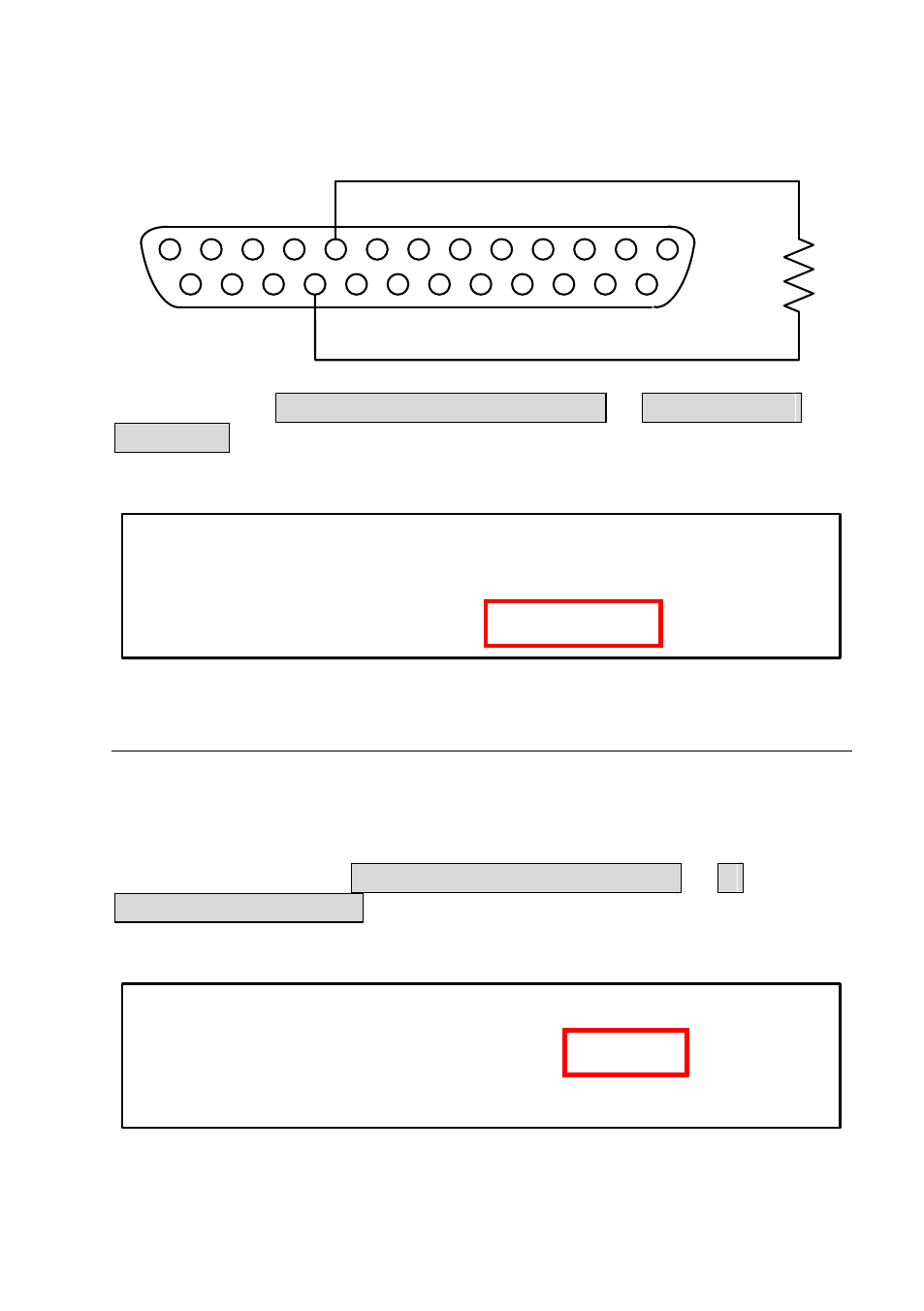
Pin 9 and GND Pin 22 can be connected with a resistor to set the power
supply’s output voltage value.
1
3
2
4
6
5
7
9
8
10
12
11
13
14
16
15
17
19
18
20
22
21
23
25
24
You may access MENU 6-SPECIAL TEST FUNC 2. EXTERNAL
CONTROL to choose the input resistance range at [EXTERN PROGRAM]
to [10 V / 10 K] for 0 – 10 k
Ω and [ 5 V / 5 K] for 0 – 5 kΩ.
EXTERN VOLT CONTROL= VOLT
EXTERN CURR CONTROL= VOLT
EXTERN PROGRAM= 10 V / 10 K
Current Program - Voltage Mode
This function allows you to program the current output by connecting an
external DC voltage to Pin 10. For this function to be enabled, the output
control must be in Analog mode. The external voltage range used to control
the full scale of the output voltage can be selected between 0 – 10 V or 0 –
5 V range. Then, access MENU 6-SPECIAL TEST FUNC 2.
EXTERNAL CONTROL to set [EXTERN CURR CONTROL =] to
[VOLT], as shown in the figure below.
EXTERN VOLT CONTROL= VOLT
EXTERN CURR CONTROL= VOLT
EXTERN PROGRAM= 10 V / 10 K