1 sensor description, 1 “high voltage” and “low voltage” sensors – Alpha Technologies PowerAgent SC3 User Manual
Page 8
PowerAgent
TM
SC3 Site Controller
Document # 700-000014-01 Rev 2
Installation and Operation
Phoenix Broadband Technologies, LLC
10/28/2010
Page 8 of 57
2.1 Sensor Description
Sensor modules are small, inexpensive units designed to
mount in close mechanical, electrical, and thermal
proximity to the monitored jar’s terminal posts. The sensor
takes a very small amount of “idling” power from the
monitored jar (typically less than 10ma). Internally, a
programmable microcontroller chip provides an optically
isolated communications interface for the site control unit.
Sensors are connected to the Site Controller using a
CAT5 cable daisy chain.
The sensor continuously monitors the voltage and
temperature of the jar. At user-defined intervals, the
microcontroller generates a digitally synthesized AC test
signal of approximately 0.5 to 6.0 amps (depending on
sensor type) which drives the jar’s terminals for testing
purposes. This test current causes a small AC voltage,
proportional to jar impedance, to be superimposed on the
jar’s DC terminal voltage. This AC voltage is separated from the DC terminal voltage and
amplified inside the sensor module. It is then fed to an analog-to-digital converter inside the
microcontroller chip. The microcontroller digitally samples the AC waveform and performs a DSP
(digital signal processing) algorithm that filters out noise and measures the amplitude of the AC
signal. These measurements and subsequent calculations determine the jar’s internal AC
impedance, which is the basis for Admittance measurements.
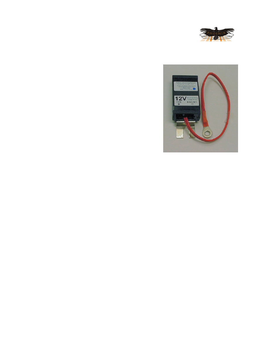
Mechanically, the sensor consists of a nickel-plated copper mounting bracket which fits on the
jar’s negative terminal post, a short wire terminated in terminal lug that connects to the jar’s
positive terminal post, and an electronics assembly that contains the test signal generation and
measurement circuitry. Sensors with two wires are also available.
The sensors with brackets have the advantage of being able to more accurately measure the
temperature of the electrolyte in the cell. The two wire sensors have the advantage of working
with a wide variety cell and jar mechanical configurations that could requires several different
bracket types. Refer to the Sensor Selector Guide later in this section for more details.
Each sensor is shipped with a 1 foot CAT5 cable to connect the sensor to the daisy chain. This
cable is the proper length for most applications. Longer cables are available from PBT.
2.1.1
“High Voltage” and “Low Voltage” Sensors
Sensors are typically used in DC power plant and UPS applications. DC power plant applications
commonly utilize two volt cells and twelve volt jars wired in series with total nominal string
voltages typically ranging from 24 to 48 VDC nominal. In many UPS systems, voltages can be
significantly higher (480 volts or more). Because of the specific requirements of high voltage
systems, Phoenix Broadband has developed two types of sensors to accommodate each
environment.
When working in environments where string voltages are greater than 64 VDC, always use the
High Voltage sensors. “High voltage” (HV) sensors are completely optically isolated from the