5 provisioning analog alarms – Alpha Technologies PowerAgent SC3 User Manual
Page 49
PowerAgent
TM
SC3 Site Controller
Document # 700-000014-01 Rev 2
Installation and Operation
Phoenix Broadband Technologies, LLC
10/28/2010
Page 49 of 57
6.5.5
Provisioning Analog Alarms
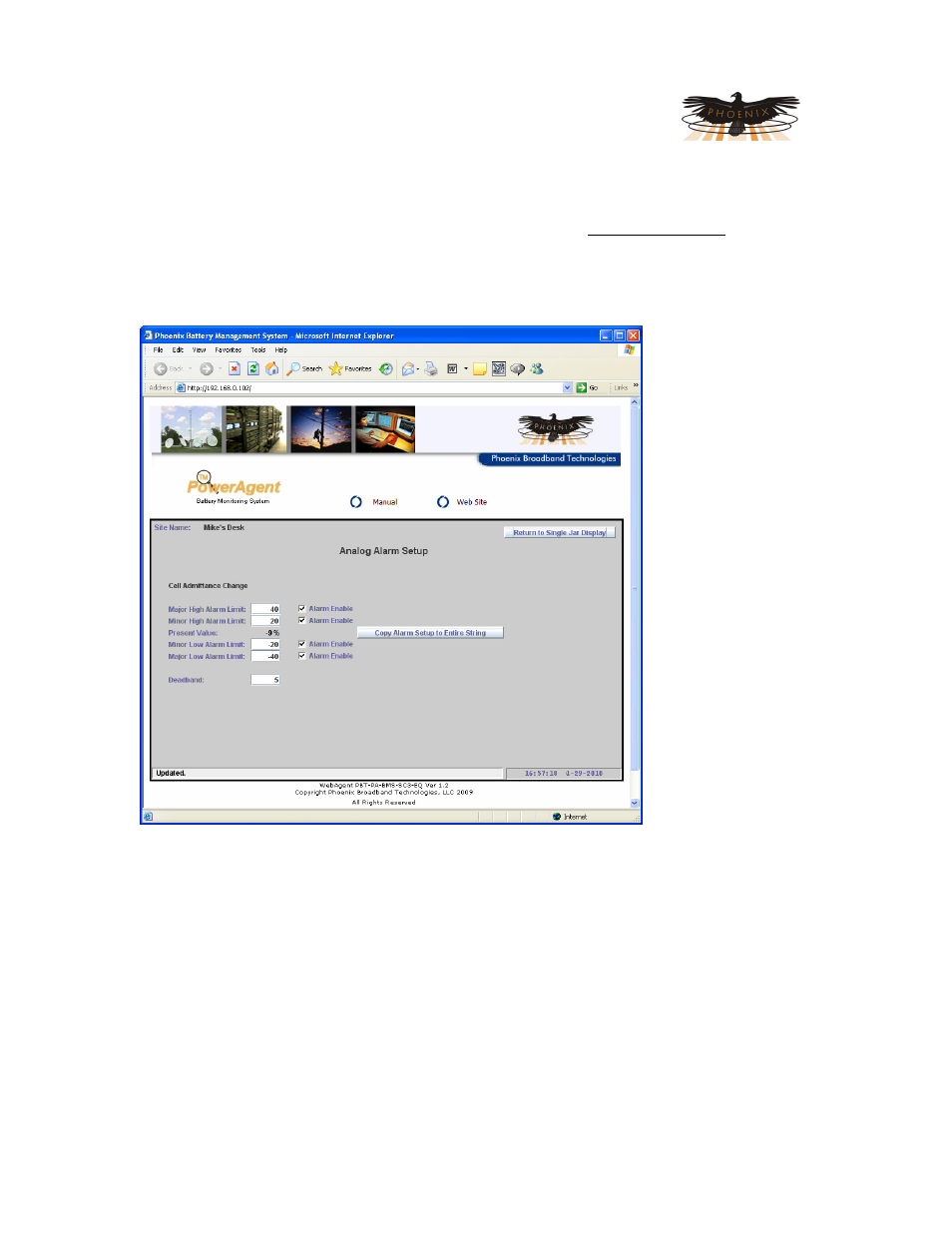
When the A button next to a measured parameter is pressed the Analog Alarm Setup screen
shown below will appear. There are 4 Alarm Limits that can be set independently and an Alarm
Enable check box for each alarm limit. When the enable box is checked, the alarm will occur
when the Present Value crosses the Alarm Limit. In the example below there is a Minor Alarm
because the Present Value is below the Minor Low Alarm Limit.
The Deadband
setting provides
hysteresis so the
alarm does not chatter
if the Present Value
is right at the alarm
limit. For High alarms
the alarm will occur
when the present
Value is greater than
the Alarm Limit. The
alarm will clear when
the Present Value is
less than the High
Alarm Limit minus
the Deadband.
Likewise for a Low
alarms, the alarm will
occur when the
present Value is less
than the Alarm Limit.
The alarm will clear
when the Present
Value is greater than
the Low Alarm Limit
plus the Deadband.
Minor and major
alarms operate independently so as the Present Value moves a minor alarm will become a major
alarm and vise versa.
Values in Yellow indicate a Minor alarm, Red indicates a Major alarm, and normal values are
block.
All alarm settings are nonvolatile and will be saved in the Site Controller database.
SNMP Traps and/or Emails may be sent whenever the alarm state changes and when the alarm
returns to the normal state. Refer to the Telnet Setup section of this manual for information on
setting the Trap destinations and Email addresses.