Extron Electronics TLP 710TV User Guide User Manual
Page 17
k
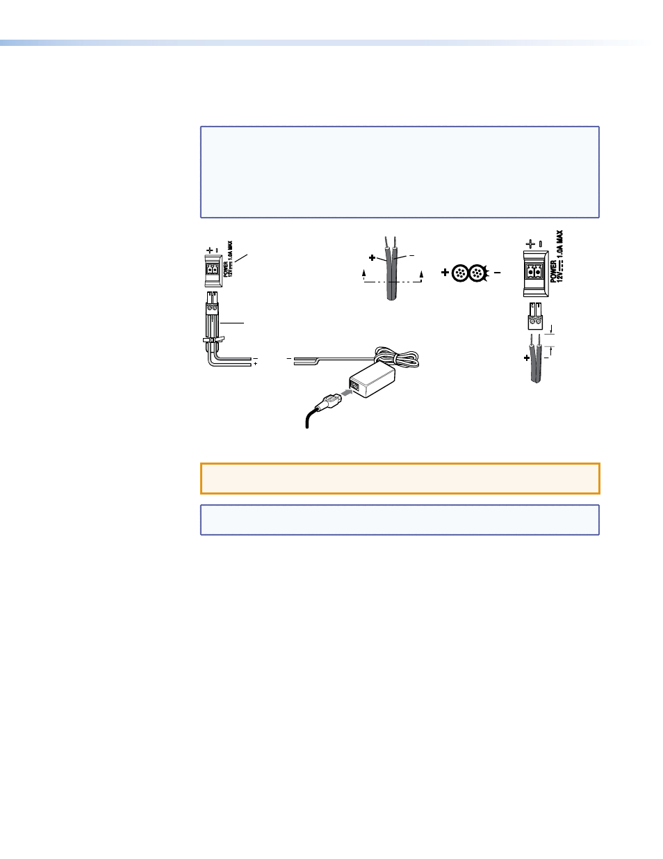
Power connector — Connect the 2-pole, 3.5 mm captive screw connector from the
12 VDC, 1.0 A power supply (not provided) to the power supply socket on the rear
panel. Ensure the connections have the correct polarity as shown in figure 10.
NOTES:
•
Extron recommends using the Power over Ethernet power supply.
The 12 VDC, 1.0 A power supply should only be used for setup or
troubleshooting.
•
If both power supplies are connected to the TLP 710TV, the PoE power
supply takes precedence.
Power Receptacle
Captive Screw Connector
AC Power Cord
Ground
+12 VDC
External
Power Supply
(12 VDC, 1 A )
SECTION A–A
Ridges
Smooth
Power Supply
Output Cord
A
A
3/16"
(5 mm) Max.
Figure 10.
Power Supply Connection
ATTENTION: See the
on page 7 for important information about
power supplies.
NOTE: See the
on page 7 for important information about wiring captive
screw connectors.
l
MTP signal adjustments — Three MTP signal adjustments are available for S-video
luminance gain (VID/Y), S-video chrominance gain (C), and sharpness (S). For
composite video signals, the gain is controlled by the VID/Y adjustment. Insert a small
Phillips head screwdriver into the recess and turn clockwise to increase adjustment or
counterclockwise to decrease.
m
VESA mounting holes — Four holes are arranged in a pattern that is in accordance
with the VESA FDMI standard, type D 75 mm (see
mounting the TLP 710TV with the Extron LPVM-1
TLP 710MV and TLP 710TV • Panel Features
11