Rainbow Electronics DS2180A User Manual
Page 8
DS2180A
041995 8/36
B8ZS
The DS2180A supports existing and emerging zero
suppression formats. Selection of B8ZS coding main-
tains system 1’s density requirements without disturb-
ing data integrity as required in emerging clear channel
applications. B8ZS coding replaces eight consecutive
outgoing 0’s with a B8ZS code word. Any received
B8ZS code word is replaced with all 0’s. B8ZS and bit 7
stuffing modes should not be enabled simultaneously.
Enabling both results in LOS.
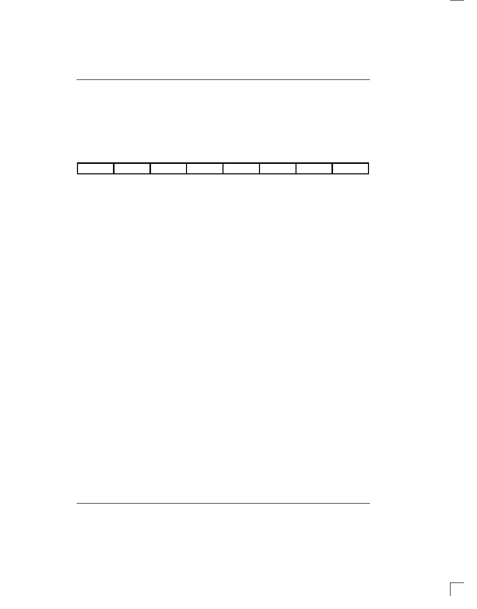
TCR: TRANSMIT CONTROL REGISTER Figure 5
(MSB)
(LSB)
ODF
TFPT
TCP
RBSE
TIS
193SI
TBL
TYEL
SYMBOL
POSITION
NAME AND DESCRIPTION
ODF
TCR.7
Output Data Format.
0 = Bipolar data at TPOS and TNEG.
1 = NRZ data at TPOS; TNEG=0.
TFPT
TCR.6
Transmit Framing Pass-through.
0 = FT/FPS sourced internally.
1 = FT/FPS sampled at TSER during F-bit time.
TCP
TCR.5
Transmit CRC Pass-through.
0 = Transmit CRC code internally generated.
1 = TSER sampled at CRC F-bit time for external CRC insertion.
RBSE
TCR.4
Robbed Bit Signaling Enable.
1 = Signaling inserted in all channels during signaling frames.
0 = No signaling inserted. (The TTR registers allow the user to disable
signaling insertion on selected DS0 channels.)
TIS
TCR.3
Transmit Idle Code Select. Determines idle code format to be inserted
into channels marked by the TIR registers.
0 = Insert 7F (Hex) into marked channels.
1 = Insert FF (Hex) into marked channels.
193SI
TCR.2
193S S-bit Insertion. Determines source of transmitted S-bit.
0 = Internal S-bit generator.
1 = External (sampled at TLINK input).
TBL
TCR.1
Transmit Blue Alarm.
0 = Disabled.
1 = Enabled.
TYEL
TCR.0
Transmit Yellow Alarm.
0 = Disabled.
1 = Enabled.
TRANSMIT BLUE ALARM
The blue alarm (also known as the AIS, Alarm Indication
Signal) is an unframed, all 1’s sequence enabled by as-
serting TCR.1. Blue alarm overrides all other transmit
data patterns and is disabled by clearing TCR.1. Use of
the TIR registers allows a framed, all 1’s alarm transmis-
sion if required by the network.
TRANSMIT YELLOW ALARM
In 193E framing, a yellow alarm is a repeating pattern
set of FF(Hex) and 00 (Hex) on the 4 KHz facility data
link (FDL). In 193S framing the yellow alarm format is
dependent on the state of bit CCR.3. In all modes, yel-
low alarm is enabled by asserting TCR.0 and disabled
by clearing TCR.0.