Rainbow Electronics DS2180A User Manual
Page 21
DS2180A
041995 21/36
RYEL OUTPUT
The yellow alarm output transitions high when a yellow
alarm is detected. A high-low transition indicates the
alarm condition has been cleared. The RYEL bit
(RSR.5) is a “latched” version of the RYEL output. In
193E framing, the yellow alarm pattern detected is 16
pattern sets of 00 (Hex) and FF (Hex) received at
RLINK. In 193S, framing the yellow alarm format is de-
pendent on CCR.3; if CCR.3=0, the RYEL output transi-
tions high if bit 2 of 256 or more consecutive channels is
0; if CCR.3=1, yellow alarm is declared when the S-bit
received in frame 12 is 1.
RBV OUTPUT
The bipolar violation output transitions high when an ac-
cused bit emerges at RSER. RBV will go low at the next
bit time if no additional violations are detected.
RFER OUTPUT
The receive frame error output transitions high at the F-
bit time and is held high for two bit periods when a frame
bit error occurs. In 193S framing, F
T
and F
S
patterns are
tested. The FPS pattern is tested in 193E framing. Addi-
tionally, in 193E framing, RFER reports a CRC error by a
low-high-low transition (one bit period wide) one half
RCLK period before a low-high transition on RMSYNC.
RESET
A high-low transition on RST clears all registers and
forces immediate receive resync when RST returns
high. This reset has no effect on transmit frame multi-
frame or channel counters. RST must be held low on
system power-up to insure proper initialization of trans-
ceiver counters and registers. Following reset, the host
processor should restore all control modes by writing
appropriate registers with control data.
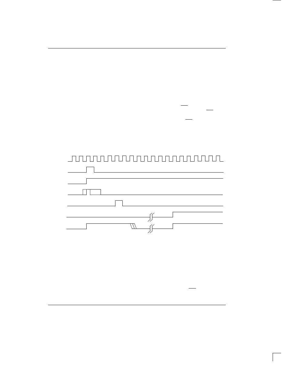
ALARM OUTPUT TIMING Figure 21
RCLK
RFSYNC
RMSYNC
RFER
1
RBV
2
RCL
3
RLOS
4
NOTES:
1. RFER transitions high during F-bit time if received framing pattern bit is in error. (Frame 12 F-bits in 193S are
ignored if CCR.3=1). Also, in 193E, RFER transitions 1/2 bit time before the rising edge of RMSYNC to indicate
a CRC error for the previous multiframe.
2. RBV indicates received bipolar violation and transitions high when an accused bit emerges from RSER. If
B8ZS is enabled, RBV will not report the zero replacement code.
3. RCL transitions high (during 32nd bit time) when 32 consecutive bits received are 0; RCL transitions low when
the next 1 is received.
4. RLOS transitions high during the F-bit time that caused an OOF event (any two of four consecutive F
T
or FPS
bits are in error) if auto-resync mode is selected (RCR.1=0). Resync will also occur when loss of carrier is de-
tected (RCL=1). When RCR.1=1, RLOS remains low until resync occurs, regardless of OOF or carrier loss
flags. In this situation, resync is initiated only when RCR.0 transitions low-to-high or the RST pin transitions
high-low-high.