Rainbow Electronics DS2180A User Manual
Page 15
DS2180A
041995 15/36
RECEIVE SIGNALING
Robbed bit signaling data is presented at RABCD dur-
ing each channel time in signaling frames for all 24 in-
coming channels. Logical combination of clocks
RMSYNC, RSIGFR and RSIGSEL allow the user to
identify and extract AB or ABCD signaling data.
RMR1–RMR3: RECEIVE MARK REGISTERS Figure 13
(MSB)
(LSB)
CH8
CH7
CH6
CH5
CH4
CH3
CH2
CH1
RMR1
CH16
CH15
CH14
CH13
CH12
CH11
CH10
CH9
RMR2
CH24
CH23
CH22
CH21
CH20
CH19
CH18
CH17
RMR3
SYMBOL
POSITION
NAME AND DESCRIPTION
CH24
RMR3.7
Receive Mark Registers. Each of these bit positions represents a DS0
CH1
RMR1.0
channel in the incoming T1 frame. When set, the corresponding channel
will output codes determined by RCR.4 and RCR.5.
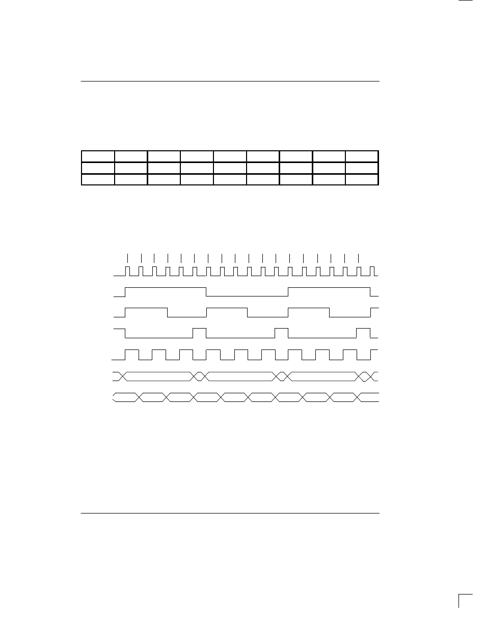
193S RECEIVE MULTIFRAME TIMING Figure 14
RLCLK
1
2
3
4
5
6
7
8
9
10
11
12
1
2
3
4
5
6
12
ЙЙЙЙЙЙЙ
ЙЙЙЙЙЙЙ
ЙЙЙЙЙЙЙ
ЙЙЙЙЙЙЙ
ЙЙЙЙЙЙЙЙ
ЙЙЙЙЙЙЙЙ
Й
Й
B
A
B
A
FRAME #
RFSYNC
RMSYNC
RSIGSEL
RSIGFR
RABCD
1
RLINK
2
NOTES:
1. Signaling data is updated during signaling frames on channel boundaries. RABCD is the LSB of each channel
word in non-signaling frames.
2. RLINK data (S-bit) is updated one bit time prior to S-bit frames and held for two frames.