Rainbow Electronics DS2180A User Manual
Page 22
DS2180A
041995 22/36
HARDWARE MODE
For preliminary system prototyping or applications
which do not require the features offered by the serial
port, the transceiver can be reconfigured by the SPS
pin. Tying SPS to V
SS
disables the serial port, clears all
internal registers except CCR and TCR and redefines
pins 14 through 18 as mode control inputs. The hard-
ware mode allows device retrofit into existing applica-
tions where mode control and alarm conditioning hard-
ware is often designed with discrete logic.
HARDWARE COMMON CONTROL
In the hardware mode bits TCR.2, CCR.4, TCR.0,
CCR.1 and CCR.2 map to pins 14 through 18. The loop-
back feature (bit CCR.0) is enabled by tying pins 17
(zero suppression) and 18 (B8ZS) to 1. (The last states
of pins 17 and 18 are latched as when both pins are tak-
en high, preserving the current zero suppression
mode). Robbed bit signaling (bit TCR.4) is enabled for
all channels. The user may tie TSER to TABCD exter-
nally to disable signaling if so desired. Bit CCR.3 is
forced to 0 which selects bit 2 yellow alarm in 193S fram-
ing. Contents of the RCR, as well as the remaining bit
locations in the CCR and TCR are cleared in the hard-
ware mode. The RST input may be used to force im-
mediate receiver resync and has no effect on transmit.
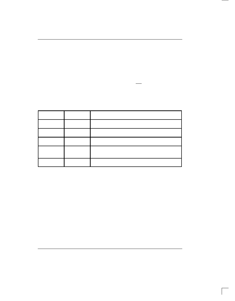
HARDWARE MODE Table 6
PIN NUMBER
REGISTER BIT
LOCATION
NAME AND DESCRIPTION
14 (16)
TCR-D2
193S – S-bit insertion
3
1 = external; 0 = internal
15 (17)
CCR-D4
Framing Mode Select.
1 = 193E; 0 = 193S
16 (18)
TCR-D0
Transmit Yellow Alarm
2 ,3
1 = enabled; 0 = disabled
17 (19)
CCR-D1
Zero Suppression
1
1 = bit 7 stuffing
0 = transparent
18 (20)
CCR-D2
B8ZS
1
.
1 = enabled; 0 = disabled
NOTES:
1. Tying pins 17 and 18 high enables loopback in the hardware mode.
2. Bit 2 (193S) and data link (193E) yellow alarms are supported.
3. S-bit yellow alarm (193S) is not internally supported; however, the user may elect to insert external S bits for
alarm purposes.
4. Pin numbers for PLCC package are listed in parenthesis.