Rainbow Electronics DS2180A User Manual
Page 29
DS2180A
041995 29/36
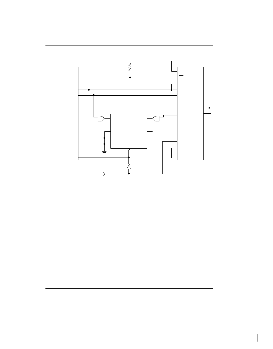
PROCESSOR-BASED TRANSMIT SIGNALING INSERTION Figure 23
SPS
INT
SDO
SDI
SCLK
CS
TSIGFR
TCHCLK
TABCD
TMSYNC
TFSYNC
INT1
P1.1
P1.0
TXD
RXD
INT0
8031/51
DS2180A
CY7C401
(64 x 4 FIFO)
TPOS
TNEG
MR
SO
Q0
Q1
Q2
Q3
SI
D0
D1
D2
D3
Multiframe Sync
19
14
15
16
18
17
8
4
9
1
2
12
10
11
1
2
13
3
4
5
6
7
15
13
12
11
10
PROCESSOR-BASED SIGNALING
Many robbed-bit signaling applications utilize a micro-
processor to insert transmit signaling data into the out-
going data stream. The circuit shown in Figure 23 “de-
couples” the processor timing from that of the DS2180A
by use of a small FIFO memory. The processor writes to
the FIFO (six bytes are written: three for A data, three for
B data) only when signaling updates are required. The
system is interrupt-driven from the transmit multiframe
sync input; the processor must update the FIFO prior to
Frame 6 (625
µ
s after interrupt) to prevent data corrup-
tion. The application circuit shown supports 193S fram-
ing. Additional hardware is required for 193E applica-
tions.