Rainbow Electronics DS2180A User Manual
Page 20
DS2180A
041995 20/36
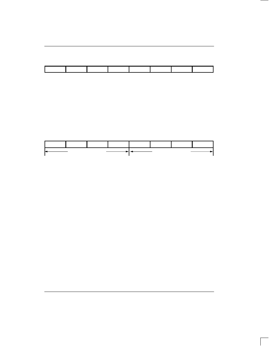
BVCR: BIPOLAR VIOLATION COUNT REGISTER Figure 19
(MSB)
(LSB)
BVD7
BVD6
BVD5
BVD4
BVD3
BVD2
BVD1
BVD0
SYMBOL
POSITION
NAME AND DESCRIPTION
BVD7
BVCR.7
MSB of bipolar count.
BVD0
BVCR.0
LSB of bipolar count.
This 8-bit binary up counter saturates at 255 and will
generate an interrupt for each occurrence of a bipolar
violation once saturated (RIMR.7=1). Presetting this
register allows the user to establish specific count inter-
rupt thresholds. The counter will count “up” to saturation
from the preset valued and may be read at any time.
Counter increments occur at all times and are not dis-
abled by resync. If B8ZS is enabled (CCR.2=1) bipolar
violations are not counted for B8ZS code words.
ECR: ERROR COUNT REGISTER Figure 20
(MSB)
(LSB)
OOFD3
OOFD2
OOFD1
OOFD0
ESFD3
ESFD2
ESFD1
ESFD0
ERROR COUNT
ESF ERROR COUNT
SYMBOL
POSITION
NAME AND DESCRIPTION
OOFD3
ECR.7
MSB of OOF event count.
OOFD0
ECR.4
LSB of OOF event count.
ESFD3
ECR.3
MSB of extended superframe error count.
ESFD0
ECR.0
LSB of extended superframe error count.
These separate 4-bit binary up counters saturate at a
count of 15 and will generate an interrupt for each occur-
rence of an OOF event or an ESF error event after satu-
ration (RIMR.6=1). Presetting these counters allows the
user to establish specific count interrupt thresholds. The
counters will count “up” to saturation from the preset val-
ue and may be read at any time. These counters share
the same register address and must be written to or read
from simultaneously.
The OOF counter records out-of-frame events in both
193S and 193E. The ESF error counter records errored
superframes in 193E. In 193S, the ESF counter records
individual F
T
and F
S
errors when RCR.3=1; F
T
errors
only when RCR.3=0. ECR counter increments are dis-
abled when resync is in progress (RLOS high).
ALARM OUTPUTS
The transceiver also provides direct alarm outputs for
applications when additional decoding and demuxing
are required to supplement the onboard alarm logic.
RLOS OUTPUT
The receive loss of sync output indicates the status of
the receiver synchronizer circuitry; when high, an off-
line resynchronization is in progress and a high-low
transition indicates resync is complete. The RLOS bit
(RSR.0) is a “latched” version of the RLOS output. If the
auto-resync mode is selected (RCR.1=0), RLOS is a
real time indication of a carrier loss or OOF event occur-
rence.