Rainbow Electronics DS2180A User Manual
Page 2
Transmit
Timing
F-Bit
Data
Data
Selector
Bipolar
Coder
Yellow
Alarm
CRC
Serial
Control
Interface
Yellow
Alarm
Detect
Information
Registers
Receive
Sync
Controller
Code
Gen
Data
Demux
Receive
Timing
Synchronizer
Bipolar
Coder
CRC
TSIGSEL
TMO
TCHCLK
TSIGFR
TPOS
TNEG
VDD
VSS
RST
TEST
RLOS
RBV
RCL
RPOS
RNEG
RCLK
RFER
TMSYNC
TFSYNC
TCLK
TLCLK
TLINK
TSER
TABCD
INT
CS
SCLK
SDI
SDO
SPS
RYEL
RSER
RABCD
RLINK
RLCLK
RSIGFR
RSIGSEL
RCHCLK
RMSYNC
RFSYNC
DS2180A
041995 2/36
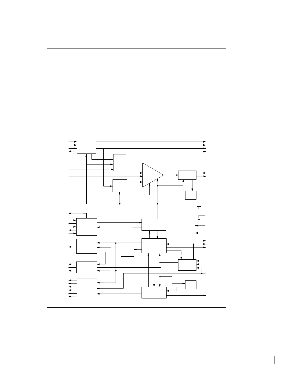
Several functional blocks exist in the transceiver. The
transmit framer/formatter generates appropriate fram-
ing bits, inserts robbed bit signaling, supervises zero
suppression, generates alarms, and provides output
clocks useful for data conditioning and decoding.
The receive synchronizer establishes frame and multi-
frame boundaries by identifying frame signaling bits, ex-
tracts signaling data, reports alarms and transmission
errors, and provides output clocks useful for data condi-
tioning and decoding.
The control block is shared between transmit and re-
ceive sides. This block determines the frame, zero sup-
pression, alarm and signaling formats. User access to
the control block is by one of two modes.
In the processor mode, pins 14 through 18 are a micro-
processor/microcontroller-compatible serial port which
can be used for device configuration, control and status
monitoring.
In the hardware mode, no offboard processor is re-
quired. Pins 14 through 18 are reconfigured into “hard-
wired” select pins. Features such as selection “clear”
DS0 channels, insertion of idle code and alteration of
sync algorithm are unavailable in the hardware mode.
DS2180A BLOCK DIAGRAM Figure 1