Rainbow Electronics W79E8213R User Manual
Page 89
Preliminary W79E8213/W79E8213R Data Sheet
Publication Release Date: July 11, 2008
- 89 -
Revision A2
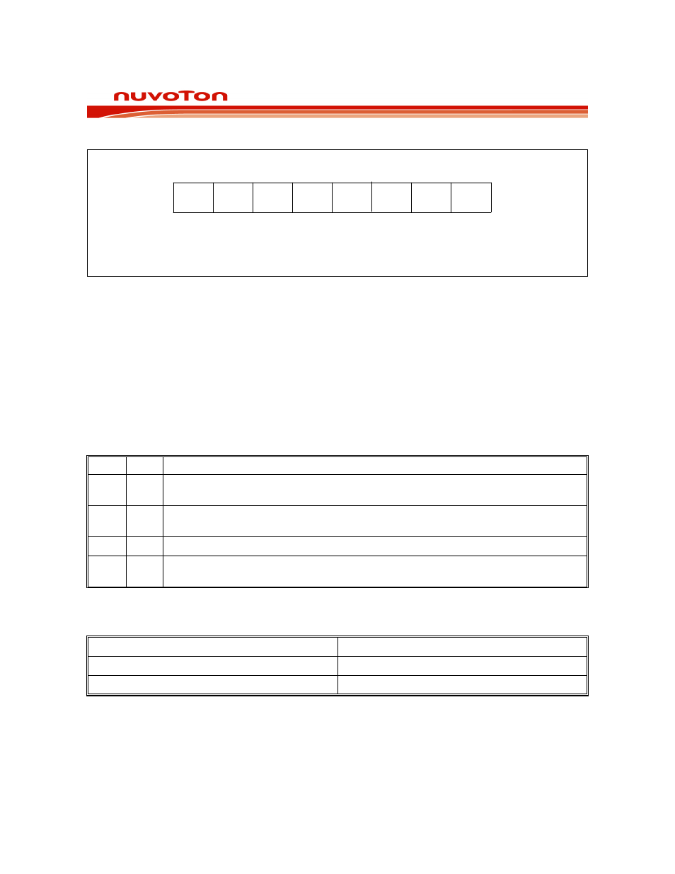
25.2 CONFIG1
7
6
5
4
3
2
1
0
C6
C7
FS1
C7
: 4K Flash EPROM Code Lock Bit
C6
: 128 byte Data Lock Bit
-
-
FS1
: Internal RC 10MHz/20MHz Selection Bit
-
-
-
Figure 25-2: Config1 register bits (W79E8213 series)
C7: 4K Flash EPROM Lock bit
This bit is used to protect the customer’s program code. It may be set after the programmer finishes
the programming and verifies sequence. Once this bit is set to logic 0, both the Flash EPROM data
and CONFIG Registers can not be accessed again.
C6: 128 byte Data Flash EPROM Lock bit
This bit is used to protect the customer’s 128 bytes of data code. It may be set after the programmer
finishes the programming and verifies sequence. Once this bit is set to logic 0, both the 128 bytes of
Flash EPROM data and CONFIG Registers can not be accessed again.
BIT 7
BIT 6
FUNCTION DESCRIPTION
1 1
Both security of 4KB program code and 128 Bytes data area are not locked. They
can be erased, programmed or read by Writer or ICP.
0 1
The 4KB program code area is locked. It can’t be read by Writer or ICP. The 128
Bytes data area can be program or read. The bank erase is invalid.
1 0
Not
supported.
0
0
Both security of 4KB program code and 128 Bytes data area are locked. They can’t
be read by Writer or ICP.
FS1: Internal RC Oscillator 10MHz/20MHz selection bit
This bit is used to select 10MHz or 20MHz internal RC oscillator.
FS1
Internal RC Oscillator Output
0 10MHz
1 20MHz
(default)
Internal Oscillator Selection Table