Rainbow Electronics W79E8213R User Manual
Page 57
Preliminary W79E8213/W79E8213R Data Sheet
Publication Release Date: July 11, 2008
- 57 -
Revision A2
If any of these conditions are not met, then the LCALL will not be generated. The polling cycle is
repeated every machine cycle, with the interrupts sampled in the same machine cycle. If an interrupt
flag is active in one cycle but not responded to, and is not active when the above conditions are met,
the denied interrupt will not be serviced. This means that active interrupts are not remembered; every
polling cycle is new.
The processor responds to a valid interrupt by executing an LCALL instruction to the appropriate
service routine. This may or may not clear the flag which caused the interrupt. In case of Timer
interrupts, the TF0 or TF1 flags are cleared by hardware whenever the processor vectors to the
appropriate timer service routine. In case of external interrupt, INT0 and INT1, the flags are cleared
only if they are edge triggered. In case of Serial interrupts, the flags are not cleared by hardware. The
Watchdog timer interrupt flag WDIF has to be cleared by software. The hardware LCALL behaves
exactly like the software LCALL instruction. This instruction saves the Program Counter contents onto
the Stack, but does not save the Program Status Word PSW. The PC is reloaded with the vector
address of that interrupt which caused the LCALL. These address of vector for the different sources
are as follows:
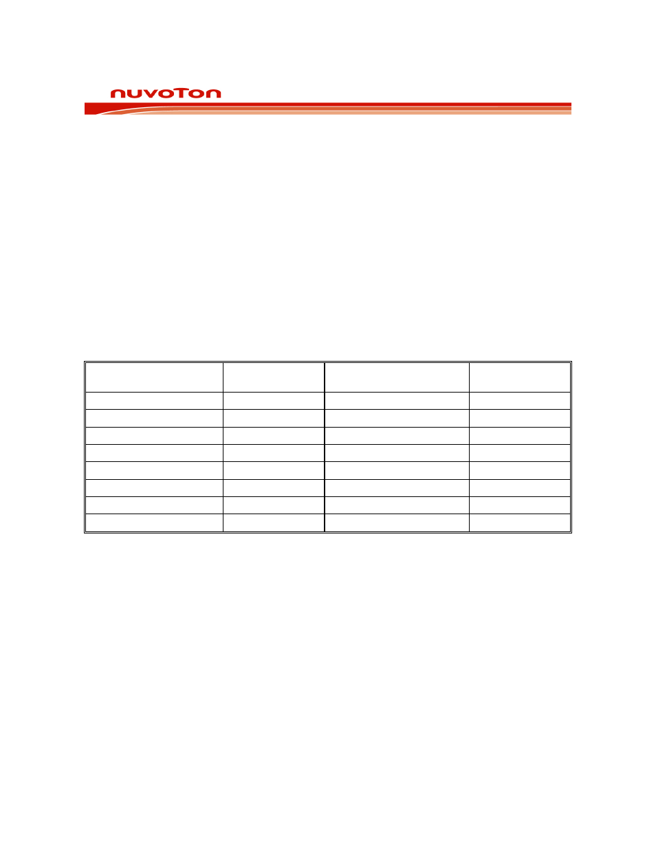
VECTOR LOCATIONS FOR INTERRUPT SOURCES
SOURCE
VECTOR
ADDRESS
SOURCE
VECTOR
ADDRESS
External Interrupt 0
0003h
Timer 0 Overflow
000Bh
External Interrupt 1
0013h
Timer 1 Overflow
001Bh
- 0023h
Brownout
Interrupt
002Bh
-
0033h
Edge Detect Interrupt
003Bh
- 0043h
- 004Bh
Watchdog Timer
0053h
ADC Interrupt
005Bh
-
0063h
PWM Brake Interrupt
0073h
PWM Underflow Interrupt
006Bh
-
007Bh
Table 12-1: Vector locations for interrupt sources
Execution continues from the vectored address till an RETI instruction is executed. On execution of
the RETI instruction the processor pops the Stack and loads the PC with the contents at the top of the
stack. The user must take care that the status of the stack is restored to what it was after the hardware
LCALL, if the execution is return to the interrupted program. The processor does not notice anything if
the stack contents are modified and will proceed with execution from the address put back into PC.
Note that a RET instruction would perform exactly the same process as a RETI instruction, but it
would not inform the Interrupt Controller that the interrupt service routine is completed, and would
leave the controller still thinking that the service routine is underway.