Rainbow Electronics W79E8213R User Manual
Page 82
Preliminary W79E8213/W79E8213R Data Sheet
Publication Release Date: July 11, 2008
- 82 -
Revision A2
PWMCON2.6 (BKPS) bit respectively. The details description of varies brake functions can be found
in the brake condition table.
Since the Brake Pin being asserted will automatically clear the Run bit of PWMCON1.7 and BKF
(PWMCON3.0) flag will be set, the user program can poll this bit or enable PWM’s brake interrupt to
determine when the Brake Pin causes a brake to occur. The other method for detecting a brake
caused by the Brake Pin would be to tie the Brake Pin to one of the external interrupt pins. This latter
approach is needed if the Brake signal is of insufficient length to ensure that it can be captured by a
polling routine. When, after being asserted, the condition causing the brake is removed, the PWM
outputs go to whatever state that had immediately prior to the brake. This means that in order to go
from brake being asserted to having the PWM run without going through an indeterminate state, care
must be taken. If the Brake Pin causes brake to be asserted, the following prototype code will allow
the PWM to go from brake and then run smoothly after brake is released.
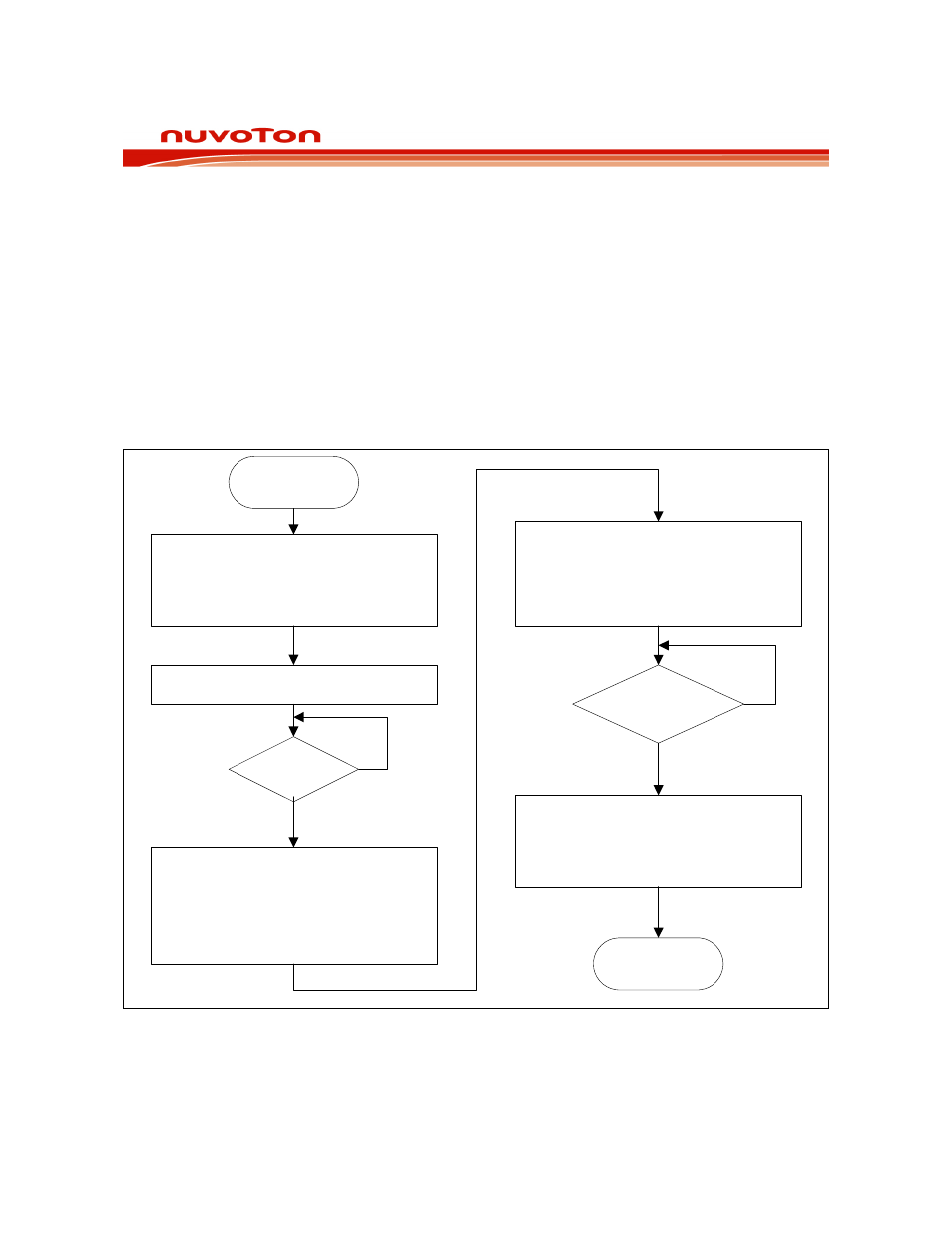
1. PWMn output=PWMnB
2. H/W set BKF=1 & PWMRUN=0
3. S/W switch to S/W Brake
(BKEN,BPEN,BKCH)=(1,0,0)
4. Set PWMn comparator output =
PWMnB or a given pattern
1. Clear 10-bit PWM counter
CLRPWM=1
2. Reload PWMP & PWM registers
3. Enable brake function
(BKEN,BPEN,BKCH)=(1,1,0)
1. Clear BKF
PWM output=PWM comparator output
2. Re-start PWM Running by setting
PWMRUN=1; load bit=1
Start
End
Initialize PWM function
1. Set PWM Control Regs
2. Set PWM brake output pattern(PWMnB)
3. Enable brake function
(BKEN,BPEN,BKCH)=(1,1,0)
PWM starts running
Brake occurs?
Yes
No
Brake pin is
asserted?
No
Yes
Figure 22-2: PWM Brake Function