Rainbow Electronics W79E8213R User Manual
Page 18
Preliminary W79E8213/W79E8213R Data Sheet
Publication Release Date: July 11, 2008
- 18 -
Revision A2
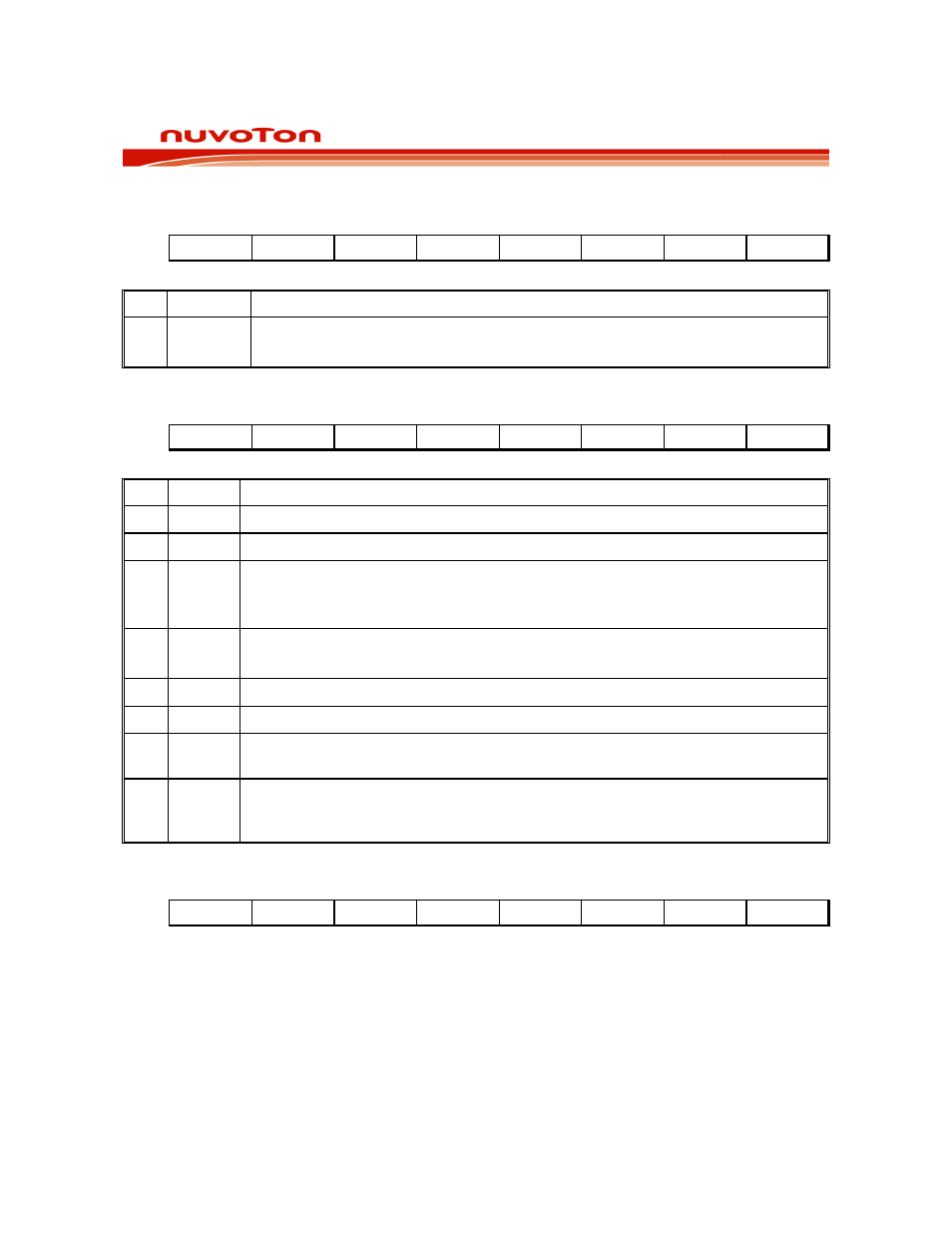
DATA POINTER HIGH
Bit:
7 6 5 4 3 2 1 0
DPH.7 DPH.6 DPH.5 DPH.4 DPH.3 DPH.2 DPH.1 DPH.0
Mnemonic: DPH
Address: 83h
BIT NAME
FUNCTION
7-0 DPH.[7:0]
This is the high byte of the standard 8052 16-bit data pointer.
This is the high byte of the DPTR 16-bit data pointer.
POWER CONTROL
Bit:
7 6 5 4 3 2 1 0
- - BOF
POR
GF1
GF0
PD
IDL
Mnemonic: PCON
Address: 87h
BIT NAME
FUNCTION
7 -
Reserved.
6 -
Reserved.
5 BOF
0: Cleared by software.
1: Set automatically when a brownout reset or interrupt has occurred. Also set at
power on.
4 POR
0: Cleared by software.
1: Set automatically when a power-on reset has occurred.
3
GF1
General purpose user flags.
2
GF0
General purpose user flags.
1 PD
1: The CPU goes into the POWER DOWN mode. In this mode, all the clocks are
stopped and program execution is frozen.
0 IDL
1: The CPU goes into the IDLE mode. In this mode, the clocks CPU clock stopped,
so program execution is frozen. But the clock to the serial, timer and interrupt
blocks is not stopped, and these blocks continue operating.
TIMER CONTROL
Bit:
7 6 5 4 3 2 1 0
TF1 TR1 TF0 TR0 IE1 IT1 IE0 IT0
Mnemonic: TCON
Address: 88h