Rainbow Electronics W79E8213R User Manual
Page 37
Preliminary W79E8213/W79E8213R Data Sheet
Publication Release Date: July 11, 2008
- 37 -
Revision A2
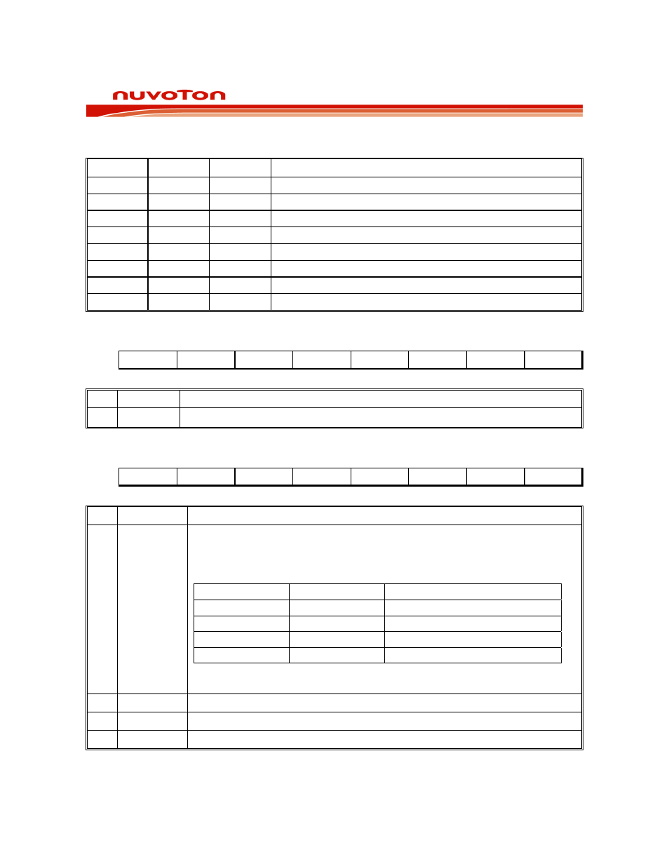
AADR1, AADR0: ADC Analog Input Channel select bits:
These bits can only be changed when ADCI and ADCS are both zero.
AADR2
AADR1
AADR0
SELECTED ANALOG INPUT CHANNEL
0 0 0
AD0
(P0.3)
0 0 1
AD1
(P0.4)
0 1 0
AD2
(P0.5)
0 1 1
AD3
(P0.6)
1 0 0
AD4
(P0.2)
1 0 1
AD5
(P0.1)
1 1 0
AD6
(P0.0)
1 1 1
AD7
(P0.7)
ADC CONVERTER RESULT HIGH REGISTER
Bit:
7 6 5 4 3 2 1 0
ADC.9 ADC.8 ADC.7 ADC.6 ADC.5 ADC.4 ADC.3 ADC.2
Mnemonic: ADCH
Address: E2h
BIT NAME
FUNCTION
7-0
ADC.[9:2]
8 MSB of 10-bit A/D conversion result.
ADC CONTROL REGISTER 1
Bit:
7 6 5 4 3 2 1 0
ADCLK.1
ADCLK.0
- - - AADR2
- -
Mnemonic: ADCCON1
Address: E3h
BIT NAME
FUNCTION
7-6 ADCLK.1~0
ADC Clock Prescaler:
The 10-bit ADC needs a clock to drive the converting and the clock frequency
need to be within 200KHz to 5MHz. ADCLK[1:0] controls the frequency of the
clock to ADC block as below table.
ADCLK.1 ADCLK.0 ADC Clock Frequency
0 0 ADCCLK/1
0 1 ADCCLK/2
1 0 ADCCLK/4
(default)
1 1 ADCCLK/8
Note: User required to clear ADCEN (ADCEN = 0) when re-configure the
ADC clock prescaler.
5-3 -
Reserved.
2
AADR2
The ADC input select. See table in SFR ADCCON.
1-0 -
Reserved.
INTERRUPT ENABLE REGISTER 1