Rainbow Electronics W79E8213R User Manual
Page 36
Preliminary W79E8213/W79E8213R Data Sheet
Publication Release Date: July 11, 2008
- 36 -
Revision A2
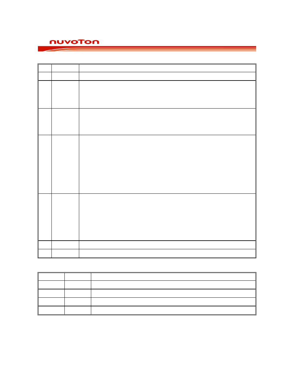
BIT NAME
FUNCTION
7-6
ADC.1-0
2 LSB of 10-bit A/D conversion result.
5 ADCEX
Enable STADC-triggered conversion
0: Conversion can only be started by software (i.e., by setting ADCS).
1: Conversion can be started by software or by a rising edge on STADC (pin
P1.4).
4 ADCI
ADC Interrupt flag:
This flag is set when the result of an A/D conversion is ready. This generates an
ADC interrupt, if it is enabled. The flag may be cleared by the ISR. While this flag
is 1, the ADC cannot start a new conversion. ADCI can not be set by software.
3 ADCS
ADC Start and Status: Set this bit to start an A/D conversion. It may also be set
by STADC if ADCEX is 1. This signal remains high while the ADC is busy and is
reset right after ADCI is set.
Note:
1.
It is recommended to clear ADCI before ADCS is set. However, if ADCI
is cleared and ADCS is set at the same time, a new A/D conversion
may start on the same channel.
2.
Software clearing of ADCS will abort conversion in progress.
3.
ADC cannot start a new conversion while ADCS is high.
2 RCCLK
0: The CPU clock is used as ADC clock source.
1: The internal RC 10MHz/20MHz (selectable by CONFIG1.FS1 bit) clock is
used as ADC clock source.
Note:
1. This bit can only be set/cleared when ADCEN=0.
2. The ADC clock source will goes through pre-scalar of /1, /2, /4 or /8,
selectable by ADCLK bits (SFR ADCCON1.6-7).
1
AADR1
The ADC input select. See table below.
0
AADR0
The ADC input select. See table below.
The ADCI and ADCS control the ADC conversion as below:
ADCI ADCS
ADC
STATUS
0 0
ADC not busy; A conversion can be started.
0 1
ADC busy; Start of a new conversion is blocked.
1 0
Conversion completed; Start of a new conversion requires ADCI = 0.
1 1
This is an internal temporary state that user can ignore it.