Rainbow Electronics W79E8213R User Manual
Page 54
Preliminary W79E8213/W79E8213R Data Sheet
Publication Release Date: July 11, 2008
- 54 -
Revision A2
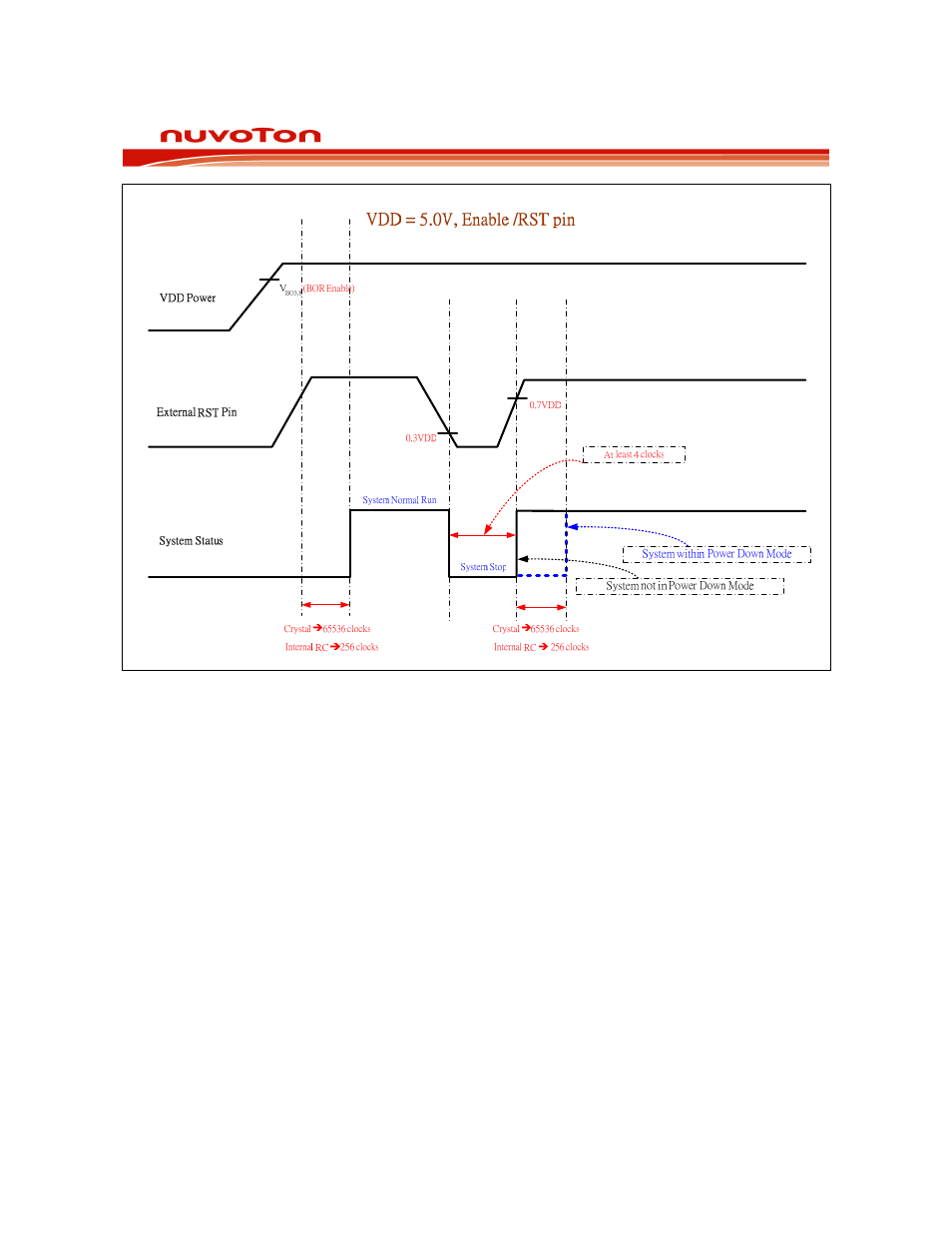
Figure 11-2: Reset and Vdd monitor timing diagram, enable /RST pin.
11.1.1 External Reset
The device samples the /RST pin every machine cycle during state C4. The /RST pin must be held
low for at least two machine cycles before the reset circuitry applies an internal reset signal. Thus, this
reset is a synchronous operation and requires the clock to be running.
The device remains in the reset state as long as /RST is low and remains low up to two machine
cycles after /RST is deactivated. Then, the device begins program execution at 0000h. There are no
flags associated with the external reset, but, since the other two reset sources do have flags, the
external reset is the cause if those flags are clear.
11.1.2 Power-On Reset (POR)
When power up, the device performs a power-on reset and sets the POR flag. The software should
clear the POR flag, or it will be difficult to determine the source of future resets. During power-on-
reset, all port pins will be tri-stated. After power-on-reset, the port pins state will determined by PRHI
value.