Rainbow Electronics W79E8213R User Manual
Page 33
Preliminary W79E8213/W79E8213R Data Sheet
Publication Release Date: July 11, 2008
- 33 -
Revision A2
BIT NAME
FUNCTION
7~0 PWM1.[7:0] PWM 1 Low Bits Register.
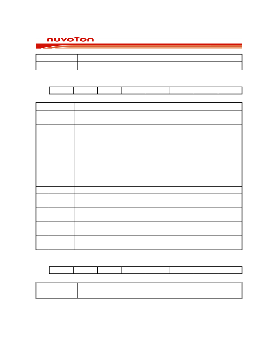
PWM CONTROL REGISTER 1
Bit:
7 6 5 4 3 2 1 0
PWMRUN
Load
PWMF
CLRPWM
- - PWM1I
PWM0I
Mnemonic: PWMCON1
Address: DCh
BIT NAME
FUNCTION
7 PWMRUN
0: The PWM is not running.
1: The PWM counter is running.
6 Load
0: The registers value of PWMP and PWMn are never loaded to counter and
Comparator registers.
1: The PWMP and PWMn registers load value to counter and compare registers
at the counter underflow. This bit is auto cleared by hardware at next clock
cycle.
5 PWMF
PWM underflow flag:
0: The 10-bit counter down count is not underflow.
1: The 10-bit counter down count is underflow. (PWM interrupt is requested if
PWM interrupt is enabled).
This bit is Software clear.
4
CLRPWM
1: Clear 10-bit PWM counter to 000H. This bit is auto cleared by hardware.
3 PWM3I
0: PWM3 out is non-inverted.
1: PWM3 output is inverted.
2 PWM2I
0: PWM2 out is non-inverted.
1: PWM2 output is inverted.
1 PWM1I
0: PWM1 out is non-inverted.
1: PWM1 output is inverted.
0 PWM0I
0: PWM0 out is non-inverted.
1: PWM0 output is inverted.
PWM2 LOW BITS REGISTER
Bit:
7 6 5 4 3 2 1 0
PWM2.7 PWM2.6 PWM2.5 PWM2.4 PWM2.3 PWM2.2 PWM2.1 PWM2.0
Mnemonic: PWM2L
Address: DDh
BIT NAME
FUNCTION
7~0 PWM2.[7:0] PWM 2 Low Bits Register.