Rainbow Electronics W79E8213R User Manual
Page 49
Preliminary W79E8213/W79E8213R Data Sheet
Publication Release Date: July 11, 2008
- 49 -
Revision A2
9.1 Instruction
Timing
This section is important because some applications use software instructions to generate timing
delays. It also provides more information about timing differences between the W79E8213 series and
the standard 8051/52.
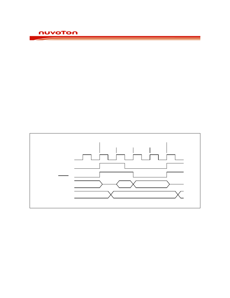
In W79E8213 series, each machine cycle is four clock periods long. Each clock period is called a
state, and each machine cycle consists of four states: C1, C2 C3 and C4, in order. Both clock edges
are used for internal timing, so the duty cycle of the clock should be as close to 50% as possible to
avoid timing conflicts.
The W79E8213 series does one op-code fetch per machine cycle, so, in most instructions, the number
of machine cycles required is equal to the number of bytes in the instruction. There are 256 available
op-codes. 128 of them are single-cycle instructions, so many op-codes are executed in just four clocks
period. Some of the other op-codes are two-cycle instructions, and most of these have two-byte op-
codes. However, there are some instructions that have one-byte instructions yet take two cycles to
execute. One important example is the MOVX instruction.
In the standard 8052, the MOVX instruction is always two machine cycles long. However, in the
W79E8213 series each machine cycle is made of only 4 clock periods compared to the 12 clock
periods for the standard 8052. Therefore, even though the number of categories has increased, each
instruction is at least 1.5 to 3 times faster than the standard 8052 in terms of clock periods.
Single Cycle
C4
C3
C2
C1
CPU CLK
ALE
PSEN
AD<7:0>
Address <15:0>
A7-0
Address A15-8
Data_ in D7-0
Figure 9-1: Single Cycle Instruction Timing