Rainbow Electronics W79E8213R User Manual
Page 81
Preliminary W79E8213/W79E8213R Data Sheet
Publication Release Date: July 11, 2008
- 81 -
Revision A2
10-bit Down Counter
Compare Register
Counter Register
PWM0 register
+
-
Compare Register
PWM1 register
+
-
Compare Register
PWM2 register
+
-
PWM0
(P0.1)
+
-
X
X
X
Y
Y
Y
>
>
>
load
PWMP Register
Clear
Counter
PWM1
(P1.6)
PWM2
(P1.7)
PWM1I
PWM2I
PWM0I
Underflow
CLRPWM
PWMRUN
Fosc
Prescaler
(1/1, 1/2, 1/4, 1/16)
Fcpwm
(FP1, FP0)
Posc
BKCH
BPEN
BKEN
Brake
Control
Block
BKF
BKPS
0
1
P0.1
PWM0B
0
1
0
1
P1.6
PWM1B
PWM2B
P1.7
Brake Pin
(P0.2)
P0.2=0
P0.2=1
1
0
Enable External Brake Pin
(BPEN,BKCH)=(1,X)
+
-
X
Y
>
PWM3
(P0.0)
PWM3I
0
1
PWM3B
P0.0
Compare Register
PWM3 register
PWMF
S/W Clear
Q
Q
SET
CLR
D
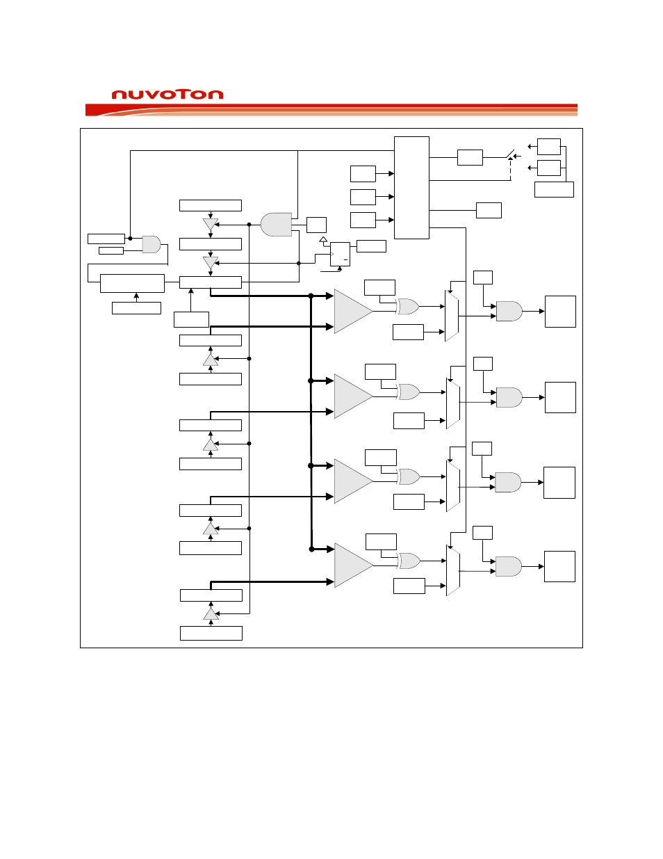
Figure 22-1: PWM Block Diagram
The W79E8213 series devices support brake function which can be activated by software or external
pin (P0.2). The Brake function is controlled by the PWMCON2 register. The setting and details
description of software brake and external pin brake can be found at the brake condition table at the
SFR section.
As for external brake, the user program can poll the brake flag (BKF) or enable PWM’s brake interrupt
to determine when the external Brake Pin is asserted and causes a brake to occur. The brake pin
(P0.2) can be set to trigger the brake function by either low or high level, by clearing or setting the