Rainbow Electronics W79E8213R User Manual
Page 75
Preliminary W79E8213/W79E8213R Data Sheet
Publication Release Date: July 11, 2008
- 75 -
Revision A2
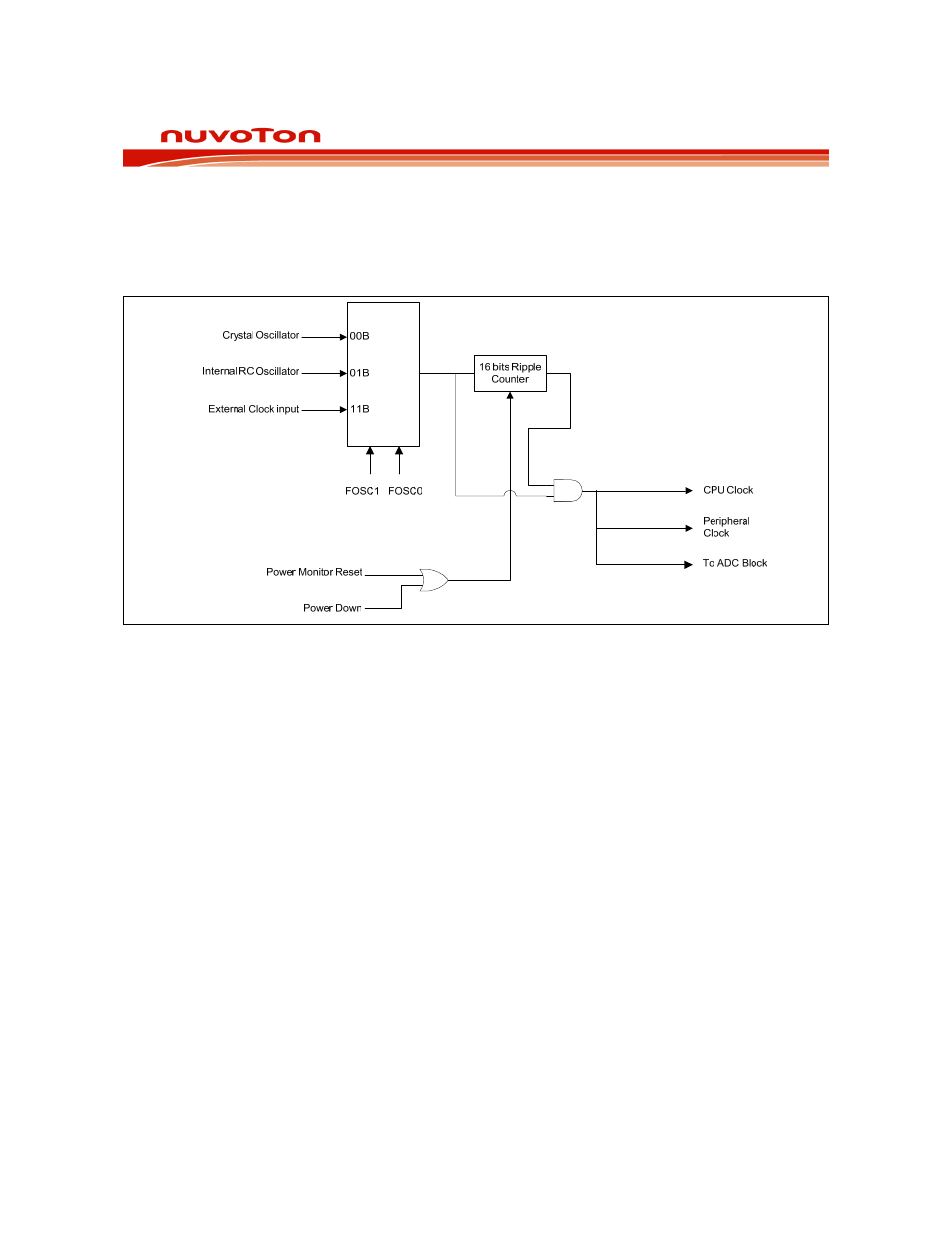
19. OSCILLATOR
The W79E8213 series provides three oscillator input option. These are configured at CONFIG register
(CONFIG0) that include Internal RC Oscillator Option, External Clock Input Option and Crystal
Oscillator Input Option. The Crystal Oscillator Input frequency may be supported from 4MHz to
20MHz, and without capacitor or resister.
Figure 19-1: Oscillator
19.1 Internal RC Oscillator Option
The internal RC Oscillator is configurable to 10MHz/20MHz (through CONFIG1.FS1 bit) frequency to
support clock source. When FOSC1, FOSC0 = 01b, the internal RC oscillator is enabled. A clock
output on P2.0 (XTAL2) may be enabled when internal RC oscillator is used.
19.2 External Clock Input Option
The clock source pin (XTAL1) is from External Clock Input by FOSC1, FOSC0 = 11b, and frequency
range is form 4MHz up to 20MHz. A clock output on P2.0 (XTAL2) may be enabled when External
Clock Input is used.
The W79E8213 series supports a clock output function when either the internal RC oscillator or the
external clock input options is selected. This allows external devices to synchronize to the W79E8213
serial. When enabled, via the ENCLK bit in the P2M1 register, the clock output appears on the
XTAL2/CLKOUT pin whenever the internal RC oscillator is running, including in Idle Mode. The
frequency of the clock output is 1/4 of the CPU clock rate. If the clock output is not needed in Idle
Mode, it may be turned off prior to entering Idle mode, saving additional power. The clock output may
also be enabled when the external clock input option is selected.