Rainbow Electronics W79E8213R User Manual
Page 32
Preliminary W79E8213/W79E8213R Data Sheet
Publication Release Date: July 11, 2008
- 32 -
Revision A2
Continued
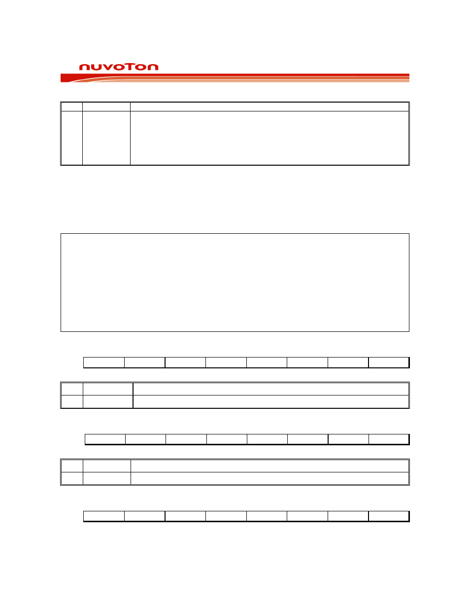
BIT NAME
FUNCTION
0 WDCLR
Reset Watchdog Timer
This bit helps in putting the watchdog timer into a know state. It also helps in
resetting the watchdog timer before a time-out occurs. Failing to set the
EWRST before time-out will cause an interrupt, if EWDI (EIE.4) is set, and 512
clocks after that a watchdog timer reset will be generated if EWRST is set. This
bit is self-clearing by hardware.
The WDCON SFR is set to 0x000000B on a reset. WTRF (WDCON.2) is set to a 1 on a Watchdog
timer reset, but to a 0 on power on/down resets. WTRF (WDCON.2) is not altered by an external
reset. EWRST (WDCON.1) is set to 0 on a Power-on reset, reset pin reset, and Watch Dog Timer
reset.
All the bits in this SFR have unrestricted read access. WDRUN, WD0, WD1, EWRST, WDIF and
WDCLR require Timed Access procedure to write. The remaining bits have unrestricted write
accesses. Please refer TA register description.
TA
REG
C7H
WDCON
REG
D8H
MOV
TA,
#AAH
;
To
access protected bits
MOV
TA,
#55H
SETB
WDCON.0
;
Reset
watchdog
timer
ORL
WDCON, #00110000B
; Select 26 bits watchdog timer
MOV
TA,
#AAH
MOV
TA,
#55H
ORL
WDCON, #00000010B
; Enable watchdog reset
PWMP COUNTER LOW BITS REGISTER
Bit:
7 6 5 4 3 2 1 0
PWMP.7 PWMP.6 PWMP.5 PWP.4 PWMP.3 PWMP.2 PWMP.1 PWMP.1
Mnemonic: PWMPL
Address: D9h
BIT NAME
FUNCTION
7~0
PWMP.[7:0]
PWM Counter Low Bits Register.
PWM0 LOW BITS REGISTER
Bit:
7 6 5 4 3 2 1 0
PWM0.7
PWM0.6
PWM0.5 PWM0.4 PWM0.3 PWM0.2 PWM0.1 PWM0.1
Mnemonic: PWM0L
Address: DAh
BIT NAME
FUNCTION
7~0
PWM0.[7:0] PWM 0 Low Bits Register.
PWM1 LOW BITS REGISTER
Bit:
7 6 5 4 3 2 1 0
PWM1.7 PWM1.6 PWM1.5 PWM1.4 PWM1.3 PWM1.2 PWM1.1 PWM1.0
Mnemonic: PWM1L
Address: DBh