Rainbow Electronics W79E8213R User Manual
Page 70
Preliminary W79E8213/W79E8213R Data Sheet
Publication Release Date: July 11, 2008
- 70 -
Revision A2
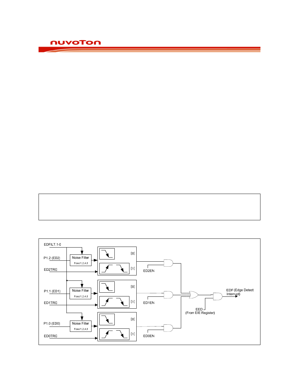
17. EDGE DETECT INTERRUPT
The W79E8213 series are provided edge detect interrupt function to detect keypad status which key is
acted, and allow a single interrupt to be generated when any key is pressed on a keyboard or keypad
connected to specific pins of the W79E8213 series, as shown below Figure. This interrupt may be
used to wake up the CPU from Idle, after chip is in Idle Mode.
Edge detect function is supported through Port 1.0-1.2. It can allow any or all pins of P1.0-P1.2 to be
enabled to cause this interrupt. Port pins are enabled by the setting of bits of ED0EN ~ ED2EN in the
EDIC register, as shown below Figure.
The edge detect trigger option is programmable through EDxTRG bits (EDIC). It supports falling
edge, and either falling edge or rising edge triggers. It also has a global digital noise filter type control
which can filter noisy edge detect inputs. The trigger pulse must be over 1 machine cycle (for Clk =
Fosc filter type), 2 machine cycles (for Clk = Fosc/2 filter type), 4 machine cycles (for Fosc/4 filter type)
and 8 machine cycles (for Fosc/8 filter type).
The Edge Detect Interrupt Flag (EDF) in the AUXR1 register is set when any enabled pin is triggered
while the ED interrupt function is active. An interrupt will be generated if it has been enabled. The EDF
bit set by hardware and must be cleared by software. Due to human time scales and the mechanical
delay associated with key-switch closures, the edge detect feature will typically allow the interrupt
service routine to poll P1.0-P1.2 in order to determine which key was pressed.
Note:
As this device support falling and rising edge triggers, user has to ensure the Edge
Detection pins at high initial state when using edge detection. This is necessary to avoid
false detection. It applies to both trigger types.