Rainbow Electronics W79E8213R User Manual
Page 87
Preliminary W79E8213/W79E8213R Data Sheet
Publication Release Date: July 11, 2008
- 87 -
Revision A2
25. CONFIG BITS
The W79E8213 series has two CONFIG bits (CONFIG0 located at FB00h, CONFIG1 located at
FB01h) that must be defined at power up and can not be set the program after start of execution.
Those features are configured through the use of two flash EPROM bytes, and the flash EPROM can
be programmed and verified repeatedly. Until the code inside the Flash EPROM is confirmed OK, the
code can be protected. The protection of flash EPROM (CONFIG1) and those operations on it are
described below. The data of these bytes may be read by the MOVX instruction at the addresses.
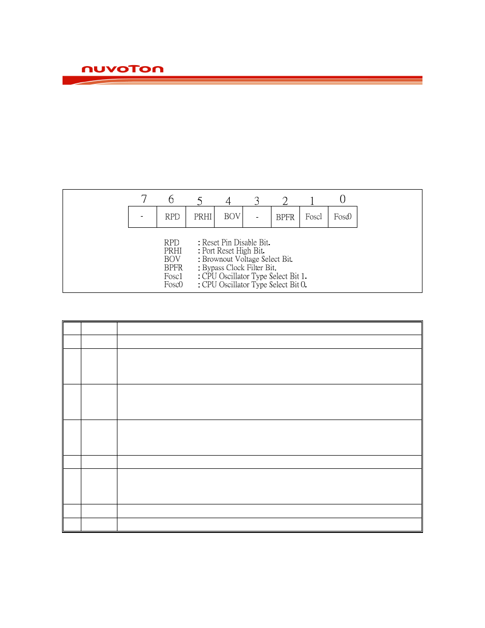
25.1 CONFIG0
Figure 25-1: Config0 register bits
BIT NAME
FUNCTION
7 -
Reserved.
6 RPD
Reset Pin Disable bit:
0: Enable Reset function of Pin 1.5.
1: Disable Reset function of Pin 1.5, and it to be used as an input port pin.
5 PRHI
Port Reset High or Low bit:
0: Port reset to low state.
1: Port reset to high state.
4 BOV
Brownout Voltage Select bit:
0: Brownout detect voltage is 3.8V.
1: Brownout detect voltage is 2.5V.
3 -
Reserved.
2 BPFR
Bypass Clock Filter.
0: Disable Clock Filter.
1: Enable Clock Filter.
1
Fosc1 CPU Oscillator Type Select bit 1.
0
Fosc0 CPU Oscillator Type Select bit 0.