Rainbow Electronics W79E8213R User Manual
Page 30
Preliminary W79E8213/W79E8213R Data Sheet
Publication Release Date: July 11, 2008
- 30 -
Revision A2
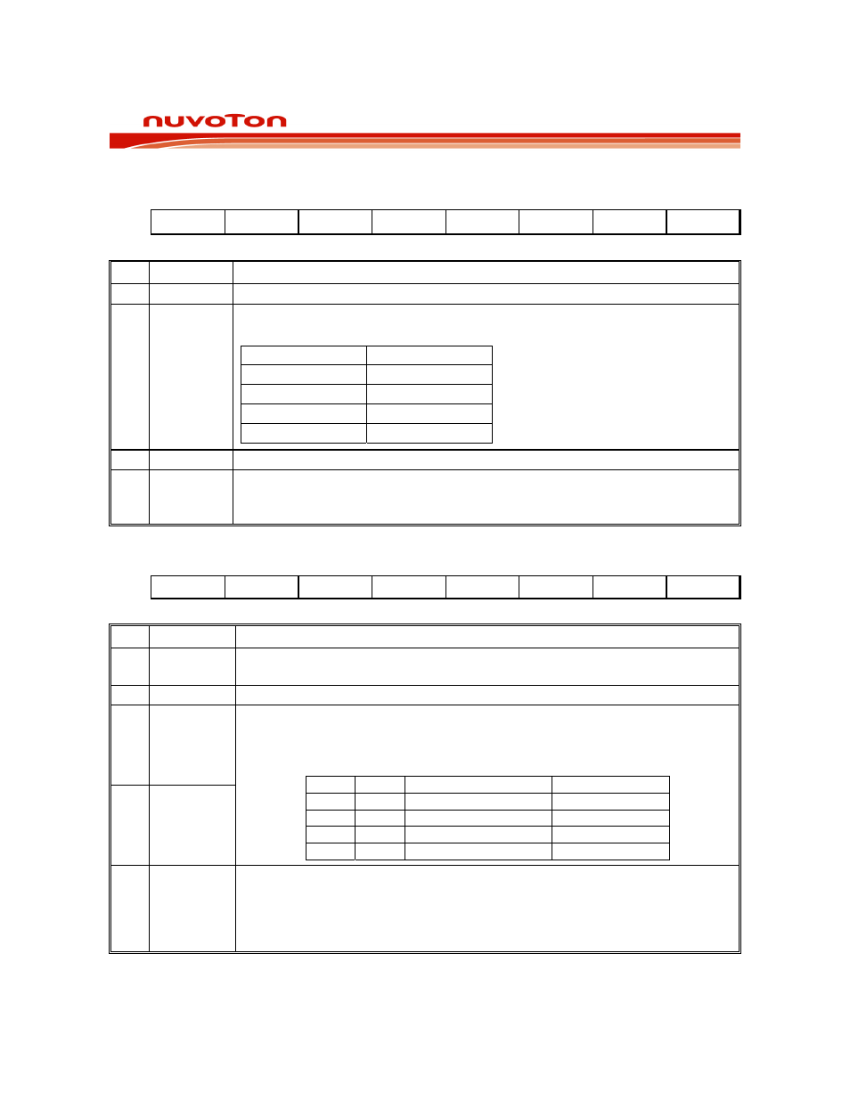
PWM CONTROL REGISTER 3
Bit:
7 6 5 4 3 2 1 0
-
-
- -
FP1 FP0 -
BKF
Mnemonic: PWMCON3
Address: D7h
BIT NAME
FUNCTION
7-4 - Reserved.
3-2 FP[1:0]
Select PWM frequency pre-scale select bits. The clock source of pre-scaler,
Fpwm is in phase with Fosc if PWMRUN=1.
FP[1:0] Fpwm
00 F
OSC
01 F
OSC
/2
10 F
OSC
/4
11 F
OSC
/16
1 -
Reserved.
0 BKF
The external brake pin flag:
0: The PWM is not brake.
1: The PWM is brake by external brake pin. It is cleared by software.
WATCHDOG CONTROL
Bit:
7 6 5 4 3 2 1 0
WDRUN
-
WD1 WD0 WDIF WTRF
EWRST
WDCLR
Mnemonic: WDCON
Address: D8h
BIT NAME
FUNCTION
7 WDRUN
0: The Watchdog is stopped.
1: The Watchdog is running.
6 -
Reserved.
5 WD1
4 WD0
Watchdog Timer Time-out Select bits. These bits determine the time-out period
of the watchdog timer. The reset time-out period is 512 clocks longer than the
watchdog time-out.
WD1
WD0
Interrupt time-out
Reset time-out
0 0
2
17
2
17
+ 512
0 1
2
20
2
20
+ 512
1 0
2
23
2
23
+ 512
1 1
2
26
2
26
+ 512
3 WDIF
Watchdog Timer Interrupt Flag
0: If the interrupt is not enabled, then this bit indicates that the time-out period
has elapsed. This bit must be cleared by software.
1: If the watchdog interrupt is enabled, hardware will set this bit to indicate that
the watchdog interrupt has occurred.