Pin descriptions – Rainbow Electronics W79E8213R User Manual
Page 7
Preliminary W79E8213/W79E8213R Data Sheet
Publication Release Date: July 11, 2008
- 7 -
Revision A2
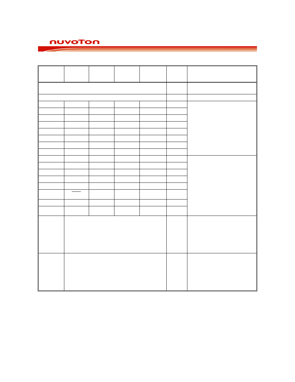
5. PIN
DESCRIPTIONS
SYMBOL
ALTERNATE
FUNCTION 1
ALTERNATE
FUNCTION 2
ALTERNATE
FUNCTION 3
ALTERNATE
FUNCTION 4
(ICP MODE)
TYPE DESCRIPTIONS
VDD
P
POWER SUPPLY: Supply voltage
for operation.
VSS
P
GROUND: Ground potential.
P0.0
AD6
PWM3 I/O
P0.1
AD5
PWM0 I/O
P0.2 AD4
BRAKE
I/O
P0.3
AD0
I/O
P0.4 AD1
Data I/O
P0.5 AD2
Clock I/O
P0.6
AD3
I/O
P0.7 AD7
T1
I/O
Port0:
Support 4 output modes and
TTL/Schmitt trigger.
Multifunction pins for T1, PWM0,
PWM3, BRAKE, AD0-7, Data
and Clock (for ICP).
P1.0 BUZ ED0
I/O
P1.1 ED1
I/O
P1.2 ED2
T0 I/O
P1.3 /INT0
I/O
P1.4 STADC /INT1
I/O
P1.5
ST
R
HV
I
P1.6 PWM1
I/O
P1.7 PWM2
I/O
Port1:
Support 4 output modes and
TTL/Schmitt trigger (except for
P1.5 input only).
Multifunction pins for /RST, T0,
/INT0-1, BUZ, PWM1-2, ED0-2,
STADC, and HV (for ICP).
P1.0-P1.7 have 40mA high sink
capability.
P2.0
XTAL2/CLKOUT
I/O
CRYSTAL2: This is the crystal
oscillator output. It is the
inversion of XTAL1. Also a
configurable i/o pin.
When operating as I/O, it
supports 4 output modes and
TTL/Schmitt trigger.
P2.1
XTAL1
I/O
CRYSTAL1: This is the crystal
oscillator input. This pin may be
driven by an external clock or
configurable I/O pin.
When operating as I/O, it
supports 4 output modes and
TTL/Schmitt trigger.
* TYPE: P: power, I: input, O: output, I/O: bi-directional, H: pull-high, L: pull-low, D: open-drain.
Table 5-1: Pin Descriptions
Note:
On power-on-reset, all port pins will be tri-stated.
After power-on-reset, all port pins state will follow CONFIG0.PRHI bit definition.