Rainbow Electronics W79E8213R User Manual
Page 19
Preliminary W79E8213/W79E8213R Data Sheet
Publication Release Date: July 11, 2008
- 19 -
Revision A2
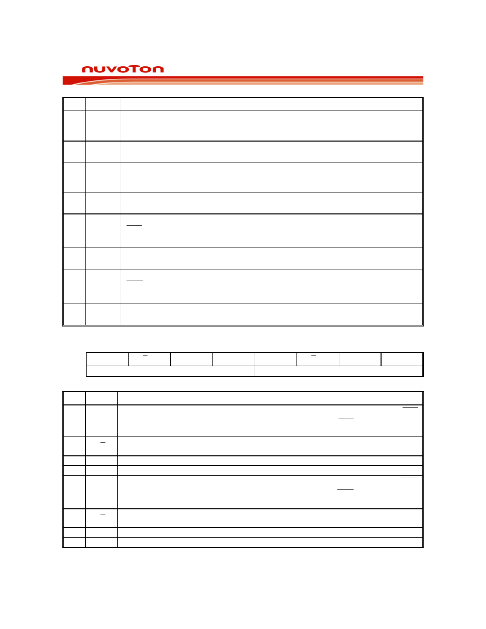
BIT NAME
FUNCTION
7 TF1
Timer 1 Overflow Flag. This bit is set when Timer 1 overflows. It is cleared
automatically when the program does a timer 1 interrupt service routine. Software
can also set or clear this bit.
6 TR1
Timer 1 Run Control. This bit is set or cleared by software to turn timer/counter on
or off.
5 TF0
Timer 0 Overflow Flag. This bit is set when Timer 0 overflows. It is cleared
automatically when the program does a timer 0 interrupt service routine. Software
can also set or clear this bit.
4 TR0
Timer 0 Run Control. This bit is set or cleared by software to turn timer/counter on
or off.
3 IE1
Interrupt 1 Edge Detect Flag: Set by hardware when an edge/level is detected on
INT1 . This bit is cleared by hardware when the service routine is vectored to only if
the interrupt was edge triggered. Otherwise it follows the inverse of the pin.
2 IT1
Interrupt 1 Type Control. Set/cleared by software to specify falling edge/ low level
triggered external inputs.
1 IE0
Interrupt 0 Edge Detect Flag. Set by hardware when an edge/level is detected on
INT0 . This bit is cleared by hardware when the service routine is vectored to only if
the interrupt was edge triggered. Otherwise it follows the inverse of the pin.
0 IT0
Interrupt 0 Type Control: Set/cleared by software to specify falling edge/ low level
triggered external inputs.
TIMER MODE CONTROL
Bit:
7 6 5 4 3 2 1 0
GATE
T
C /
M1 M0 GATE T
C /
M1 M0
TIMER1
TIMER0
Mnemonic: TMOD
Address: 89h
BIT NAME
FUNCTION
7 GATE
Gating control: When this bit is set, Timer/counter 1 is enabled only while the INT1
pin is high and the TR1 control bit is set. When cleared, the INT1 pin has no effect,
and Timer 1 is enabled whenever TR1 control bit is set.
6
T
C/
Timer or Counter Select: When clear, Timer 1 is incremented by the internal clock.
When set, the timer counts falling edges on the T1 pin.
5
M1
Timer 1 mode select bit 1. See table below.
4
M0
Timer 1 mode select bit 0. See table below.
3 GATE
Gating control: When this bit is set, Timer/counter 0 is enabled only while the INT0
pin is high and the TR0 control bit is set. When cleared, the INT0 pin has no effect,
and Timer 0 is enabled whenever TR0 control bit is set.
2
T
C/
Timer or Counter Select: When clear, Timer 0 is incremented by the internal clock.
When set, the timer counts falling edges on the T0 pin.
1
M1
Timer 0 mode select bit 1. See table below.
0
M0
Timer 0 mode select bit 0. See table below.
M1, M0: Mode Select bits: