Rainbow Electronics W79E8213R User Manual
Page 28
Preliminary W79E8213/W79E8213R Data Sheet
Publication Release Date: July 11, 2008
- 28 -
Revision A2
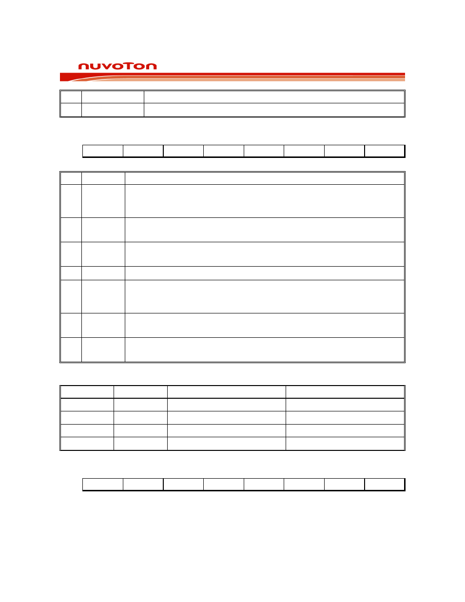
BIT NAME
FUNCTION
7~0 NVMDATA.[7:0]
The NVM data write register. The read NVM data is by MOVC instruction.
PROGRAM STATUS WORD
Bit:
7 6 5 4 3 2 1 0
CY AC F0 RS1
RS0
OV F1 P
Mnemonic: PSW
Address: D0h
BIT NAME
FUNCTION
7 CY
Carry flag:
Set for an arithmetic operation which results in a carry being generated from the
ALU. It is also used as the accumulator for the bit operations.
6
AC
Auxiliary carry:
Set when the previous operation resulted in a carry from the high order nibble.
5 F0
User flag 0:
The General purpose flag that can be set or cleared by the user.
4~3 RS1~RS0 Register bank select bits.
2 OV
Overflow flag:
Set when a carry was generated from the seventh bit but not from the 8th bit as
a result of the previous operation, or vice-versa.
1 F1
User Flag 1:
The General purpose flag that can be set or cleared by the user software.
0 P
Parity flag:
Set/cleared by hardware to indicate odd/even number of 1's in the accumulator.
RS.1-0: Register Bank Selection Bits:
RS1 RS0
REGISTER
BANK
ADDRESS
0 0
0
00-07h
0 1
1
08-0Fh
1 0
2
10-17h
1 1
3
18-1Fh
PWMP COUNTER HIGH BITS REGISTER
Bit:
7 6 5 4 3 2 1 0
- - - - - - PWMP.9
PWMP.8
Mnemonic: PWMPH
Address: D1h