Memory, Figure 1. memory map, Maxq3108 low-power, dual-core microcontroller – Rainbow Electronics MAXQ3108 User Manual
Page 9
MAXQ3108
Low-Power, Dual-Core Microcontroller
_______________________________________________________________________________________
9
movement involves only source and destination mod-
ules, circuit switching activities are limited to active
modules only. For power-conscious applications, this
approach localizes power dissipation and minimizes
switching noise. The modular architecture also provides
maximum flexibility and reusability, which are important
for a microprocessor used in embedded applications.
The MAXQ instruction set is designed to be highly
orthogonal. All arithmetical and logical operations can
use any register along with the accumulator. Data move-
ment is supported from any register to any other regis-
ter. Memory is accessed through specific data pointer
registers with auto increment/decrement support.
Memory
The MAXQ3108 supports a pseudo-Von Neumann
memory structure that can merge program and data into
a linear memory map. This is accomplished by mapping
the data memory into the program space or mapping
the program memory segment into the data space.
Memory access is under the control of the memory man-
agement unit (MMU). During flash programming, the
MMU maps the flash memory into data space, and the
built-in firmware provides necessary controls to the
embedded flash memory for all read/erase/write opera-
tions when the ROM loader is invoked. Additionally,
when the DSPCore is disabled, all its code SRAM (8KB)
is mapped into the data SRAM space of the UserCore.
This allows streamlined reconfiguration of the DSP code
memory or a larger data SRAM for applications not
employing DSPCore operation.
The MAXQ3108 incorporates the following:
• 4KB utility ROM
• 64KB program flash
• 2KB SRAM data memory
• 8KB program SRAM (DSPCore)
• 1KB SRAM data memory (DSPCore)
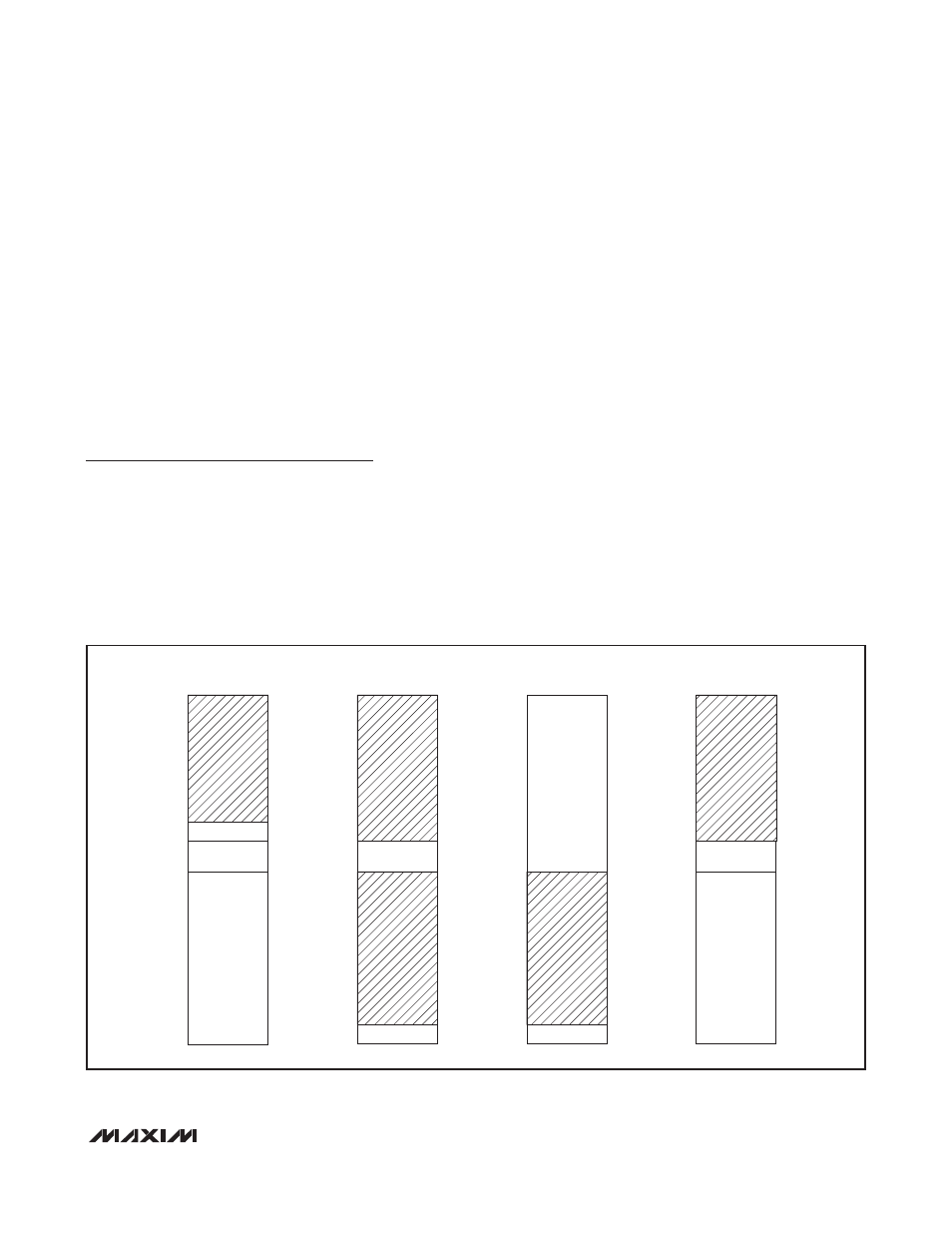
The MMU operates automatically and maps data mem-
ory as a function of the contents of the instruction point-
er; that is, the execution location controls the structure
of the data memory map. The only constraint is that no
memory region is available as data when code is being
fetched from that region. For example, when executing
from flash, flash cannot be read as data. But changing
the execution location to the utility ROM through a sub-
routine call allows the flash memory to be read as data.
CODE
DATA
WHEN EXECUTING FROM UTILITY ROM
DATA
WHEN EXECUTING FROM FLASH
DATA
WHEN EXECUTING FROM RAM
RAM 0.5kW
RAM 0.5kW
0xA800
0xA000
0x8000
0x0000
UTILITY ROM
2kW
0xA000
0x8000
0x0000
0x0800
RAM 0.5kW
0x0000
0x0000
0x0800
0x8000
UTILITY ROM
2kW
0xA000
0x8000
UTILITY ROM
2kW
FLASH
32kW
FLASH
32kW
FLASH
32kW
Figure 1. Memory Map