Maxq3108 low-power, dual-core microcontroller – Rainbow Electronics MAXQ3108 User Manual
Page 47
MAXQ3108
Low-Power, Dual-Core Microcontroller
______________________________________________________________________________________
47
Special Function Register Bit Descriptions (continued)
TB0CN.5: TBOE
Timer B Output Enable. Setting this bit to 1 enables the clock output function on the TBA pin if
C/TB = 0. Timer B rollovers do not cause interrupts. Clearing this bit to 0 allows the TBA pin to
function as either a standard port pin or a counter input for timer B.
TB0CN.6: EXFB
External Timer B Trigger Flag. When configured as a timer (C/TB = 0), a negative transition on the
TBB pin causes this flag to be set if (CP/RLB = EXENB = 1) or (CP/RLB = DCEN = 0 and EXENB =
1) or (CP/RLB = 0 and EXENB = 1 and TBCS:TBCR<>00b). When configured in any of these ways,
this flag can be set independent of the state of the TRB bit (e.g., EXFB can still be set on detection
of a negative edge when TRB = 0). When CP/RLB = 0 and DCEN = 1 and TBCS:TBCR = 00b, EXFB
toggles whenever timer B underflows or overflows.
An overflow/underflow condition is the same as described in the TFB bit description. In this mode,
EXFB can be used as the 17th timer bit and does not cause an interrupt. If set by a negative
transition, this flag must be cleared by software. Setting this bit to 1 forces a timer interrupt if
enabled.
TB0CN.7: TFB
Timer B Overflow Flag. This bit is set when timer B overflows from TBR or the count is equal to
0000h in down-count mode. It must be cleared by software.
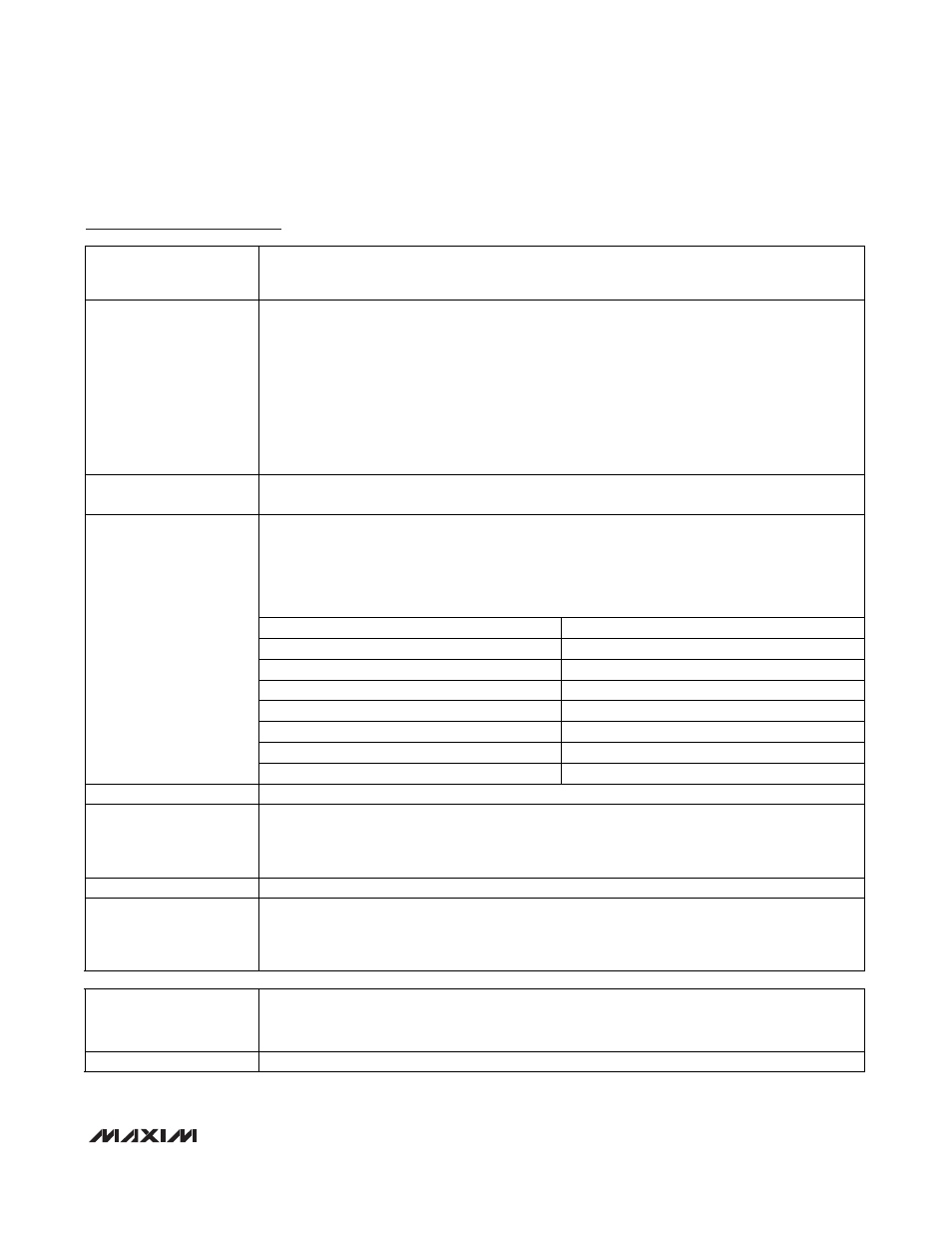
Timer B Clock Prescaler Bits 2:0. The TBPS[2:0] bits select the clock prescaler applied to the
system clock input to timer B. The TBPS[2:0] bits should be configured by the user when the timer
is stopped (TRB = 0). While hardware does not prevent changing the TBPS[2:0] bits when the timer
is running, the resultant behavior is indeterministic.
Timer B Clock = System Clock/2
(2 x TBPS[2:0])
TBPS[2:0]
TIMER B INPUT CLOCK
000 Sysclk/1
001 Sysclk/4
010 Sysclk/16
011 Sysclk/64
100 Sysclk/256
101 Sysclk/1024
TB0CN.[10:8]: TBPS[2:0]
11x Sysclk/1
TB0CN.11.TBCR
TBB Pin Output Reset Mode
TB0CN.12:TBCS
TBB Pin Output Set Mode. These mode bits define whether the PWM-mode output function is
enabled on the TBB pin, the initial output starting state, and what compare-mode output function is
in effect. Note that the TBB pin still has certain input functionality when the PWM output function is
enabled.
TB0CN.[14:13]: Reserved
Reserved. Reads return 0.
TB0CN.15: C/TB
Counter/Timer Select. This bit determines whether timer B functions as a timer or counter. Setting
this bit to 1 causes timer B to count negative transitions on the TBA pin. Clearing this bit to 0
causes timer B to function as a timer. The speed of timer B is determined by the TBPS[2:0] bits of
TBCN.
TB0V (0Bh, 04h)
Timer B 0 Value
Initialization:
This register is cleared to 0000h on all forms of reset.
Read/Write Access:
Unrestricted read/write.
TB0V.[15:0]:
Timer B Value Bits 15:0. This register is used to load and read the 16-bit timer B value.