Peripherals, Pins, Table 5. multipurpose pin description – Rainbow Electronics MAXQ3108 User Manual
Page 50: Maxq3108 low-power, dual-core microcontroller
MAXQ3108
Low-Power, Dual-Core Microcontroller
50
______________________________________________________________________________________
Special Function Register Bit Descriptions (continued)
I2CTO (0Eh, 04h)
I
2
C Timeout Register (8-Bit Register)
Initialization:
This register is cleared to 00h on all forms of reset.
Read/Write Access:
Unrestricted read/write access.
I2CTO.[7:0]:
I
2
C Timeout Register Bits 7:0. This register is used only in master mode. This register determines
the number of I
2
C bit periods (SCL high + SCL low) the I
2
C master will wait for SCL to go high. The
timeout timer resets to 0 and starts to count after the I2CSTART bit is set or every time the SCL
goes low. When cleared to 00h, the timeout function is disabled and the I
2
C waits for SCL to go
high indefinitely during a transmission. When set to any other values, the I
2
C waits until the
timeout expires and sets the I2CTOI flag.
I
2
C Timeout = I
2
C Bit Rate x (I2CTO[7:0] + 1)
Note that these bits have no effect when the I
2
C module is operating in slave mode (I2CMST = 0).
When operating in slave mode, SCL is controlled by an external master.
I2CSLA (0Fh, 04h)
I
2
C Slave Address Register (16-Bit Register)
Initialization:
This register is cleared to 0000h on all forms of reset.
Read/Write Access:
Unrestricted read/write access.
I2CSLA.[9:0]:
I
2
C Slave Address Register Bits 9:0. These address bits contain the address of the I
2
C device.
When a match to this address is detected, the I
2
C controller automatically acknowledges the
transmitter with the I2CACK bit value if the I
2
C module is enabled (I2CEN = 1). The I2CAMI flag is
set to 1 and the I2CMST bit is cleared to 0. An interrupt is generated to the CPU if enabled.
I2CSLA.[15:10]: Reserved
Reserved. Reads return 0.
Peripherals
This section contains detailed descriptions for each
peripheral device, however, many of the peripherals
are described in detail in the
MAXQ User’s Guide
.
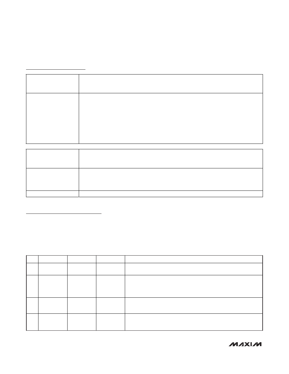
Pins
Most of the peripheral devices on the MAXQ3108
require connections to other components. To minimize
the pin count, some peripherals share pins with other
peripherals. Obviously, only one peripheral can drive a
pin at any given time. Table 5 provides information on
how to use these multipurpose pins.
PIN
PRIMARY
SECONDARY
TERTIARY
COMMENT
1 P2.0 MDIN2P MOSI
Do not enable both Manchester decoder 2 and SPI at the same time. If
neither is enabled, the GPIO port function is used.
2 P0.0
TXD0
INT0
Transmit data is only presented to the pin when a character is actually
being transmitted. To use this pin as full-time transmit data, set the GPIO
port pin to output and load a 1 in the output register. Do not enable an
interrupt on this pin if it is used for the serial transmit function.
3
P0.1 RXD0 INT1
Receive data function is only operational when the associated REN bit is
set is the SCON0 register. Do not enable an interrupt on this pin if it is
used for the serial receive function.
4 P0.2 MDIN1N T2P
Do not enable outputs or clock gating on timer 2 when Manchester
decoder 1 is enabled. Also, do not enable INT2 when Manchester
decoder 1 is enabled or clock gating is used on timer 2.
Table 5. Multipurpose Pin Description